Unity Shader
参考书籍《Unity Shader 入门精要》 – 冯乐乐(一位在图形渲染方面很厉害的女生)
使用的Unity版本:
Unity 5.4.0f3
Rendering
关于图形渲染相关知识以及OpenGL相关学习参见:
Computer_Graphic_Study
OpenGL_Study
Unity Shader
首先让我们通过官网的一张图来看看Unity Shader里面占据重要地位的3D Model,Material,Shader之间的关系: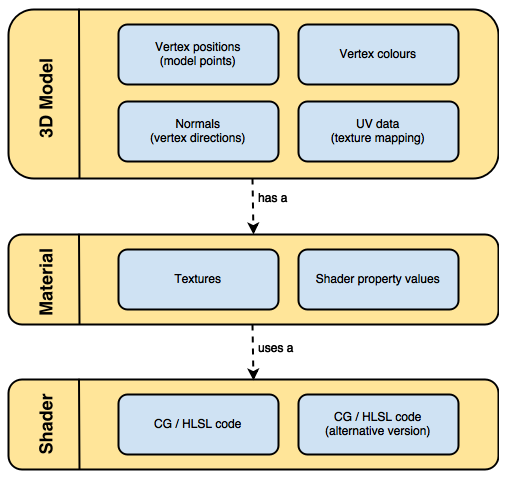
可以看出Material会决定使用哪些Texture和Shader去渲染Model。
Shader是针对Texture和Model去做运算的地方。
Unity Shader最主要的有两种(还有Image Effect Shader,Computer Shader等后续会学习):
- Surface shader
Time to use – “Whenever the material you want to simulate needs to be affected by lights in a realistic way, chances are you’ll need a surface shader. Surface shaders hide the calculations of how light is reflected and allows to specify “intuitive” properties such as the albedo, the normals, the reflectivity and so on in a function called surf.”
可以看出Unity的Surface Shader帮我们把光照对物体的影响的计算抽象了出来。我们只需设定一些控制系数,然后通过Surface Shader的surf方法就能触发光照作用对表面的运算。
下面简单看下官网给出的Surface Shader Code:
1 | CGPROGRAM |
Note:
必须使用#pragma surface去表示是surface shader
Surface Shader的Code是包含在SubShader里的并且必须写在CGPROGRAM和ENDCG标识之间。
- Fragment and Vertex Shaders
Fragment and Vertex Shaders就跟OpenGL里差不多,model的vertex会经历完整的Shader Pipeline,最终通过计算得出最终的颜色。
让我们来看看官网给出的Fragment and Vertex Shaders Code:
1 | Pass { |
可以看出vert方法好比OpenGL里vertex shader的main函数入口。
frag方法好比OpenGL里fragment shader的main函数入口。
这里frag方法return的half4相当于OpenGL FS里的FragColor。
可以看出我们还是需要在VS里先将vertex变换到透视投影坐标系,然后最后传递给FS,FS计算出最终的颜色。
Note:
这里需要注意的一点是,在VS和FS Shader里,code是包含在Pass {…..}里的。
让我们来看看官网给出的Shader的大体结构:
1 | Shader "MyShader" |
Properties:
“The properties of your shader are somehow equivalent to the public fields in a C# script; they’ll appear in the inspector of your material, giving you the chance to tweak them.”
从这里看出Properties在Unity里相当于OPENGL Shader里定义的Uniform,Sampler,全局变量等,用于作为可控的输入。
让我们来看看官网给出的例子
1 | Properties |
让我们先看看对应显示在Unity面板是什么模样: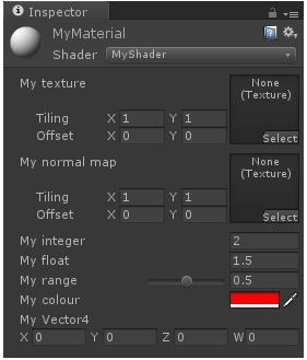
2D代表_MyTexture,_MyNormalMap是texture类型.Color代表颜色。Range代表范围值……
可以看到Properties里定义的变量都显示在了Unity面板里用于控制。但是真正通过Shader去访问,我们还需要在SubShader里重新定义对应的变量。
SubShader:
1 | SubShader |
可以看出Texture在Unity Shader里面的定义和在OpenGL Shader里差不多,也是通过sampler2D,只是不再需要加uniform修饰了。
这里值得注意的是Color对应的不是Vector4而是half4。
还有就是在Properties里定义的变量名在SubShader要一一对应。
接下来让我们看看官网给出的SubShader里Shader具体是怎样的格式:
1 | SubShader |
真正的Shader Code是在CGPROGRAM和ENGCG里。
这里需要先提一下Tags的作用,Tags是为了告诉Unity我们Shader的特定属性(比如RenderType-渲染类型,Queue–渲染顺序)。
Surface Shaders
让我们看看Surface Shader的大体流程:
下图来源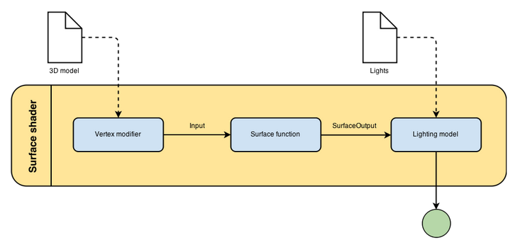
从上图可以看出,Surace Shader通过Surface function生成最终参与光照计算所需的数据(rendering properties – e.g. texture……)。
让我们来看看Surface Shader里的关键组成部分:
- Surface function
Surface function把model data作为输入,把rendering properties作为输出,这些rendering properties最后会参与光照的计算得到最终颜色。 - Input
Input structure一般包含了texture相关的信息(比如 UV坐标信息),也可以包含一些额外信息(参见)
Note:
定义texture coordinate的时候必须以uv或者uv2开头加texture名字。 - SurfaceOutput
SurfaceOutput描述了surface的属性,这些属性最终会参与光照计算。
1 | struct SurfaceOutput |
我们可以通过Shader去计算上面参与光照计算的属性去影响Surface的最终效果,从而达到Surface Shader的真正目的。
- Light Model
Light Model是真正通过SurfaceOutput属性去计算光照的地方,通过使用或编写不同的Light Model我们可以实现不同的光照影响效果。
那么如何定义光照运算函数了?- half4 Lighting
(SurfaceOutput s, half3 lightDir, half atten);
因为没有viewDir所以这里是用于不需要知道观察点的Ambient光照计算 - half4 Lighting
(SurfaceOutput s, half3 lightDir, half3 viewDir, half atten);
因为有了viewDir,知道了观察点信息,我们可以计算出需要知道观察点的Diffuse和Specular光照。 - half4 Lighting
_PrePass (SurfaceOutput s, half4 light);
这个用于Deferer Shading(但这里我比较好奇的是如果要计算Diffuse和Specular光照还是需要知道lightDir和viewDir等信息才对。)
Note:
自定义光照模型的时候,我们不需要定义所有的光照函数,只需定义我们需要的即可。
- half4 Lighting
- Vertex Function
Provide the ability to change vertices before sending them to surf.
定义方式如下:
1 | void vert(inout appdata_full v){......} |
appdata_full包含了所有vertex相关的信息
- Finalcolor Function
用于对经过Surface Shader处理后的pixel进行最后的处理。
格式如下:
1 |
|
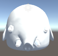
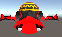
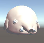
接下来让我们通过创建自己的Surface Shader来感受下Surface Shader实际运用效果(这里我拿了SurviveShooter里的模型做输入):
以下学习参考至Surface shaders in Unity3D
我们删掉默认创建的Shader Code,只简单输出Albedo(Diffuse Color)看看效果:
1 | Shader "Custom/TonyShader" { |
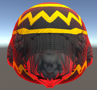
接下来让我们给Hellephant加上纹理图案:
1 | Shader "Custom/TonyShader" { |
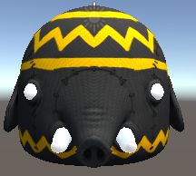
让我们看看现在对应的Unity Material Editor: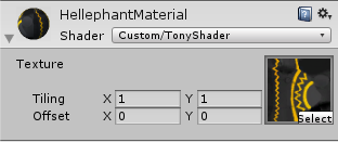
图像看起来还不真实,没有深度感,接下来我们添加Normal Mapping 参见:
1 | Shader "Custom/TonyShader" { |
UnpackNormal接受一个fixed4的输入,并将其转换为所对应的法线值(fixed3)
比较有无Normal map的效果,见如下: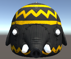
接下来让我们通过计算Normal和Viedir的情况去高亮物体:
这里需要用到build-in variable viewDir(代表观察者看顶点的方向)
1 | Shader "Custom/TonyShader" { |
saturate的作用是把观察者方向和顶点法线夹角Cos值限定在[0,1],再用1减去这个值,表明观察者方向和顶点法线夹角越小rim值越小,当夹角大于等于90度的时候达到rim最大值。从而实现高亮边缘的效果(周边和观察者角度往往比较大)。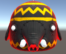
接下来我们看看通过vertex function去动态计算新vertex值的效果(这里我们根据顶点法线方向去收缩顶点postion):
1 | Shader "Custom/TonyShader" { |
在vert function里我们也可以自定义一些成员在surface shader里传递,但这样的话vert必须有两个参数,一个inout appdata_full v,一个out Input o,这里的out Input o回座位surf function的Input IN参数作为输入。Custom Input Member详细用法参见
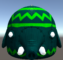
接下来让我们看看Light Model对于最终颜色计算的影响:
待学习了解
最后我们来看看Final Color Function是如何影响最终颜色计算的:
1 | Shader "Custom/TonyShader" { |
Vertex and Fragment Shaders
见后续Shader学习
Unity Shader入门精要
渲染管线
参考以前的学习:
Computer_Graphic_Study
OpenGL_Study
Unity Shader基础
材质和Unity Shader
结合前面的学习,我们知道了在Unity里Material会决定使用那些Texture和Shader去渲染Model。
这里再简单梳理下他们之间的关系:
- Model(模型) – 最终我们需要通过渲染去实现特定效果的模型。(提供模型数据 e.g. 顶点,法线等)
- Texture(贴图数据) – 这里没有直接说成纹理是因为Texture不仅能提供纹理数据,还能提供作为其他计算的数据(e.g. 光照方面的数据等)
- Material(材质) – 会决定使用哪些Texture作为数据输入(e.g. 纹理数据,光照计算相关数据等)。通过指定Shader去处理Model和Texture等传入的数据进行处理。而材质面板是与Shader沟通的桥梁,允许我们通过面板暴露Shader暴露出的参数进行渲染控制。
- Shader – 处理前面传入的Model,Texture等数据加以处理计算实现各式各样的渲染效果。
Unity Shader分类:
- Standard Surface Shader – 前面我们提到的提供了一个包含标准光照模型计算的表面着色器。(最终还是会被编译成对应图形API接口的Vertex and Fragment Shader)
- Unlit Shader – 不包含光照的Vertex and Fragment 。Shader,需要自己编写完整的渲染管线流程代码。
- Image Effect Shader – 主要用于实现各种屏幕后处理效果。
- Compute Shader – 利用GPU的并行性进行一些与常规渲染流水线无关的计算。
这里我们主要学习Unlit Shader。
Shader对于Unity而言也是一种资源文件,所以依然有导入设置: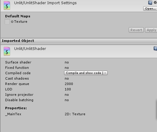
Note:
Unity Shader最终还是会被编译成对应图形编程接口(e.g. DX,OpenGL……)的Shader代码实现真正的渲染。
ShaderLab
“ShaderLab是Unity提供的编写Unity Shader的一种说明性语言。ShaderLab类似于CgFX和DX Effects语言。
“(引用自《Unity Shader入门精要》)
ShaderLab帮助我们快速定义Shader编写过程中需要资源和设置等。Unity会最终把ShaderLab编写的Shader编译成对应平台的真正代码和Shader文件,实现跨平台。
Unity Shader结构
这里我们创建一个基本的UnlitShader,结合里面的代码来学习理解(详情参考代码里的注释):
1 | // 材质索引Shader时的路径 |
数学相关知识
参考书籍:
《3D数学基础:图形与游戏开发》
《Fundamentals of Computer Graphics (3rd Edition)》 — Peter Shirley, Steve Marschnner
《Real-Time Rendering, Third Edition》 — Tomas Akenine-Moller, Eric Haines, Naty Hoffman
这里只说几点DX和OpenGL还有Unity之间需要注意的特殊点:
- 坐标系
DX和Unity使用的是左手坐标系。
OpenGL使用的是右手坐标系。 - 行列向量
DX使用的是行向量(矩阵乘法是右乘)
OpenGL和Unity使用的是列向量(矩阵乘法是左乘) - 正交矩阵
因为正交矩阵M(T)=M(-1)
在提前得知是正交矩阵的前提下可以直接使用M(T)(转置矩阵)快速求的M(-1)(逆矩阵)(e.g. 旋转是正交的)
逆矩阵可以用于快速回复之前的矩阵变化 - 44矩阵
| M(33) t(31)|
| 0(13) 1 |
M(33)代表线性变换(e.g. 旋转,缩放,错切,径向,正交投影…..)
t(31)代表平移变换
0(1*3)代表零矩阵
1代表标量1 - 纹理坐标
OpenGL中(0,0)是左下角
DX中(0,0)是左上角
关于渲染流程里的坐标系转换相关知识参考之前的学习:
Coordinate Transformations & Perspective Projection
Unity Shader的内置变量参考:
UnityShaderVariables.cginc
Unity Shader学习之旅
本人使用的Unity版本为5.4.0f3 Personal
一个最简单的顶点/片元着色器
依然采用代码实战,跟之前Unity Shader结构讲的类似,但更细节一些,相关解释都写在注释里了:
1 | Shader "Custom/SimpleShader" |
Unity内置文件和变量
[Unity Shader内置文件官网下载地址](http://unity3d.com/cn/get-unity/download/
archive)
内置文件包含文件:
1 |
内置Shader目录结构: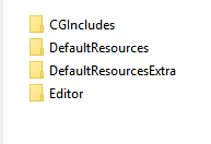
- CGIncludes – 包含所有的内置包含文件
- DefaultResources – 包含了一些内置组件或者功能需要的Unity Shader
- DefaultResourcesExtra – 包含了所有的Unity中内置的Unity Shader
- Editor – 只有一个脚本,定义了Unity 5引入的Standard Shader所有的材质面板
常用包含文件介绍:
- UnityCG.cginc – 包含了常用的帮助函数,宏和结构体等
- UnityShaderVariables.cginc – 包含了许多内置的全局变量,e.g. UNITY_MATRIX_MVP
- Lighting.cginc – 包含了各种内置的光照模型
- HLSLSupport.cginc – 声明了很多用于跨平台编译的宏和定义
Note:
Unity Shader内置文件如果安装时下载安装了,也可以在Editor\Data\CGIncludes目录下找到所有内置文件
CG/HLSL语义
“语义实际上就是让Shader知道从哪里读取数据,并把数据输出到哪里。”
“SV代表的含义是系统数据(system-value)。DX10以后引入的。大部分时候SV_POSITION和POSITION是等价的。但为了更好的跨平台最好尽量采用SV开头的语义来修饰。”
Shader Debugger
欲善其事,必先利其器。
在学习Unity Shader之前我们需要知道如何去调试Unity Shader。
Color Info
在渲染的时候把数据信息以颜色的方式渲染到物体上,用于了解特定数据信息。
Unity Frame Debugger
Unity提供的的帧调试器,是基于Unity API层面。(Window -> Frame Debug)
VS Graphics Debugger
VS提供的基于渲染API层面的调试器。
Unity Shader里要写#pragma enable_d3d11_debug_symbols开启DX11渲染
具体调试方法参考:
Implementing Fixed Function TexGen in Shaders Debugging DirectX 11 shaders with Visual Studio
Note:
Frames can only be captured if Unity is running under DirectX 11(只能基于DX11)
NVIDIA NSight
NVIDIA公司提供的基于渲染API层面的调试器。
之前了解过,好像只支持N卡。具体没有使用过。
Unity中的基础光照
光照知识回顾
关于光照的基本学习参考之前OpenGL中的学习:
Light and Shadow
从上面可以看出Light影响着每一个物体最终颜色的成像计算。
- 环境光(Ambient) – 环境光与光照方向无关,只需考虑方向光的颜色和方向光所占比重,决定着物体的基本颜色。
- 漫反射(Diffuse) – 与光照的方向和顶点normal有关,决定着不同角度(顶点法线)的顶点反射能力。
- 镜面反射(Specular) – 与光照的方向和eye观察还有顶点normal有关,决定了不同观察位置的反射高光系数。
标准光照模型
“光照模型 – 根据材质属性(如漫反射属性等),光源信息(如光源方向,辐照度),使用一个等式去计算沿某个方向的出射度的过程。”
BRDF(Bidirectional Reflectance Distribution Function)光照模型
“当给定射入光线的方向和辐射度后,BRDF可以给出在某个出射方向上的光照能量分布。”
那么什么是标准光照模型了?
“标准光照模型只关心直接光照,也就是那些直接从光源发射出来照射到物体表面后,经过物体表面的一次反射直接进入摄像机的光线。”
标准光照模型有四部分组成:
- 自发光(emissive)
- 高光反射(specular)
- 漫反射(diffuse)
- 环境光(ambient)
从这里可以看出之前学习OpenGL的光照计算可以算是基于标准光照模型来计算的,只是没有考虑自发光的光照运算。不难看出所谓的光照模型其实就是不同的光照计算公式。
在之前OpenGL的学习里,都是通过顶点法线插值后在Fragment Shader里计算Specular,Diffuse,Ambient来进行光照运算的,这种技术被称为Phong着色(Phong Shading)。(针对每一个fragment进行光照运算)
我们也可以针对每一个顶点进行光照运算,e.g. 高洛德着色(Gouraud shading)。针对每个顶点计算光照后,通过线性插值后最终输出显示。(因此不适合非线性的光照计算显示)
但上述标准光照模型(这里称为Blinn-Phong模型)无法模拟真实的物理现象的效果。
“Blinn-Phong模型是各项同性(isotropic)的,也就是说,当我们固定视角和光源方向旋转这个表面时,反射不会发生任何改变。各向异性(anisotropic)反射性质的效果需要机遇物理的光照模型来运算。”
漫反射光照模型
兰伯特光照模型
c(light) – 光源颜色信息
m(diffuse) – 漫反射系数
n – 顶点法线
l – 光源方向
兰伯特光照模型:
c(diffuse) = (c(light) * m(diffuse)) * max(0, dot(n,l))
基于顶点的兰伯特光照模型Shader:
1 | // Upgrade NOTE: replaced '_World2Object' with 'unity_WorldToObject' |
基于片元计算的兰伯特光照模型Shader:
1 | // Upgrade NOTE: replaced '_World2Object' with 'unity_WorldToObject' |
问题:
背光区域没有明暗变化看起来像一个平面。
半兰伯特(Half Lambert)光照模型
c(light) – 光源颜色信息
m(diffuse) – 漫反射系数
n – 顶点法线
l – 光源方向
a – a倍漫反射辐射度
b – 漫反射辐射度偏移量
半兰伯特光照模型:
c(diffuse) = c(light) * m(diffuse) * (a * dot(n,l) + b)
基于片元的半拉伯特特光照模型:
1 | // Upgrade NOTE: replaced '_World2Object' with 'unity_WorldToObject' |
Note:
半兰伯特光照模型没有对漫反射辐射度负值做max处理,而是通过a倍缩放加上b偏移量得出最终的漫反射辐射度,这样一来背面漫反射辐射度也会被映射到不同的值,从而拥有不同的漫反射效果。
高光反射光照模型
c(light) – 光源颜色信息
m(specular) – 材质高光反射系数
v – 视角方向
r – 反射方向
n – 顶点法线
l – 光源方向
m(gloss) – 发光系数
r可以通过n和l计算出来:
r = 2 * dot(-n,l) * n + l
跟OpenGL一样,Unity提供了直接计算反射光线方向的API:reflect(i,n)
c(specular) = (c(light) * m(specular)) * pow(max(0,dot(v,r)), m(gloss))
上面这个公式和之前在OpenGL之前学习的高光反射并没有太多出入,详情参考
这里主要要区分Phong光照模型和Blinn-Phong光照模型:
- Phong光照模型
c(specular) = (c(light) * m(specular)) * pow(max(0,dot(v,r)), m(gloss))
dot(v,r) – 是指观察者所在位置和完美反射光线之间夹角 - Blinn-Phong光照模型
h = (v + l) / |v + l|
c(specular) = (c(light) * m(specular)) * pow(max(0,dot(n,h)), m(gloss))
dot(n,h) – 是指将v和l向量归一化后的向量与n之间的夹角
可以看出来两者在计算高光反射的发光基准系数时采用了不同的运算方式。虽然两者都是经验模型,但后者是对于前者的一种改进方式。
跟漫反射一样,高光反射的计算依然有基于顶点和基于片元之分。
基于片元的Phhong高光反射光照模型代码:
1 | // Upgrade NOTE: replaced '_Object2World' with 'unity_ObjectToWorld' |
基于片元的Blinn-Phhong高光反射光照模型代码:
1 | // Upgrade NOTE: replaced '_Object2World' with 'unity_ObjectToWorld' |
效果图: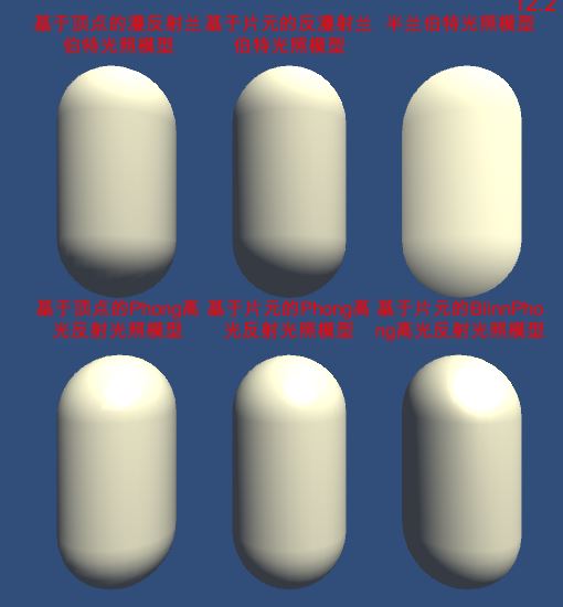
Note:
“如果没有全局光照技术,这些自发光的表面并不会真的着凉周围的物体,而是它本身看起来更亮了而已。”
计算机图形学的第一定律:如果它看起来是对的,那么它就是对的。
上面的运算都是我们通过基础的向量,矩阵运算来实现。在Unity中我们可以使用Unity内置的函数来帮助我们快速的计算得到指定结果。详情查看UnityCG.cginc。
Note:
“如果没有全局光照技术,这些自发光的表面并不会真的着凉周围的物体,而是它本身看起来更亮了而已。”
计算机图形学的第一定律:如果它看起来是对的,那么它就是对的。
Lighting in Unity
Global illumination, or ‘GI’, is a term used to describe a range of techniques and mathematical models which attempt to simulate the complex behaviour of light as it bounces and interacts with the world.(GI代表通过技术或者数学模型模拟光照运算交互。e.g. 半兰伯特(Half Lambert)光照模型
Light在Unity主要分为Realtime(相当于Forward Rendering)和Precomputed(预先生成相关光照贴图数据参与光照计算)
Realtime Lighting
directional, spot and point, are realtime. This means that they contribute direct light to the scene and update every frame.(实时的顾名思义实时计算光照)
有了实时光照计算为什么还需要Precomputed了?
Unfortunately, the light rays from Unity’s realtime lights do not bounce when they are used by themselves. In order to create more realistic scenes using techniques such as global illumination we need to enable Unity’s precomputed lighting solutions.(从官方原文来看,实时光照并没有计算光照被其他物体反弹之后的运算量,要想更加真实的光照所以需要Precomputed Lighting)
Precomputed Lighting
Static Lightmap(Baked GI Lighting):
Lightmap – When ‘baking’ a ‘lightmap’, the effects of light on static objects in the scene are calculated and the results are written to textures which are overlaid on top of scene geometry to create the effect of lighting.(Bake GI Light会生成一张LightMap,这张Lightmap记录了场景里所有静态物体的光照运算结果。)
Note:
静态Lightmap一旦生成就不能再被运行时修改,实现不了场景里光照动态变化的效果
Realtime Lightmap(Baked Realtime GI Lighting):
Realtime GI Lightmap弥补了Static Lightmap的不足,可以实现预先计算所有实时光照(这里的实时光照是指全局光照(含间接光照的影响计算)))需要的数据去参与运行时全局光照计算。
To speed up the precompute further Unity doesn’t directly work on lightmaps texels, but instead creates a low resolution approximation of the static geometry in the world, called ‘clusters’.(Unity为了加快Precompute速度,Lightmap的运算并不是texels级而是clusters级,可以理解成相对粗糙一点的精确度)
具体使用哪种光照策略取决于用户实际情况(显存,内存,GPU,CPU等)。
Baked Light Rules:
- Only Static GameObject才会参与Baked Lighting。
- Light Bake Mode取决于光照的Bake设置。
- Mixed的Bake Mode即会参与Bake也会参与Realtime。
- 具体Bake设置见Window -> Lighting(设置Bake Static Lightmap还是Realtime)
Note:
Precomputed Lighting是个典型空间换时间的例子。通过预算生成大量的光照信息Lightmap来避免大量的实时光照运算。
Using both Baked GI and Precomputed Realtime GI together in your scene can be detrimental to performance. A good practise is to ensure that only one system is used at a time, by disabling the other globally. (官方建议,Baked GI和Precomputed Realtime GI两者选其一不建议同时使用,避免性能问题)
Bake Realtime Lighting实战
- Realtime Resolution
Realtime Resolution is the number of realtime lightmap texels (texture pixels) used per world unit.(一个world unit使用多少个纹理贴图的像素)
这个参数会影响最终Bake出来的光照采样计算结果,同时也会影响Precompute的时间消耗。合适的值取决于场景对于光照采样精度的需求与Bake时间之间的平衡。如果场景小(比如室内)且光源很多那么精度高一点Bake时间长一点是有意义的。如果场景大(比如室外)光源变化不大,那么精度高对最终的采样光照计算结果并没有太大影响只会增加Bake时间,那这样是不值得的。
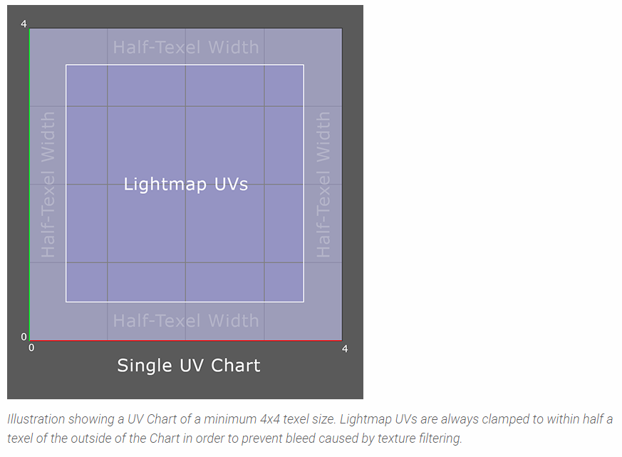
- Chart(光照图)
a Chart is an area of a lightmap texture to which we map the lightmap UVs of a given Scene object. We can think of this as a small tile containing an image of the lighting affecting that object.(Chart表示一个光照贴图,用于映射特定Object的Lightmap UV的信息)
A Chart is made up of two parts: irradiance (lighting) and directionality (encoding the dominant light direction).(Chart由两部分组成:辐射度和光照方向)
Note:
Unity Unit设置的不同对于Realtime Resolution的选择也会有影响。
Baked GI是生成一张Lightmap Texture用于运行时参与光照计算。Baked Realtime Lighting是将信息存到Lighting Data Asset(包含了运行时生成低分辨率lightmap的相关信息)里用于运行时生成低解析度的光照图。
Chart is a minimum of 4x4 texels(Chart最小是4*4像素)。
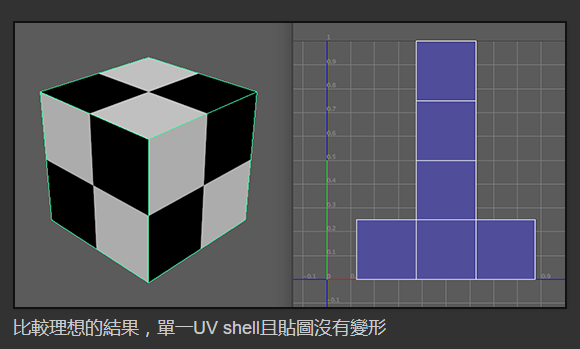
Charts are created to encompass the UV lightmap coordinates of a Static Mesh Renderer. The number of Charts that an object requires is therefore largely determined by the number of UV shells (pieces) needed to unwrap the object in question.(光照图(Charts)的目的主要是用来包住静态网格着色器(Static Mesh Renderer)的UV贴图坐标。一个物件所需要的光照图数量主要是看物体有多少片UI Shell需要拆解。)
降低Chart的数量是减少Precompute Time的关键因素之一。
除了选择合适的Realtime Resolution,还有什么方式可以帮助我们降低Chart数量了?
- 降低Static物体的UV Shells(相当于减少特定物体所需的Lightmap Chart)
- 减少Static物体(用Lighting Probe实现)
- 减少Clusters数量(PRGI基础运算单元)
在减少UV Shells数量之前,先了解下背后的原理,以及相关帮助和查看窗口:
官方的UV Shells拆分示例: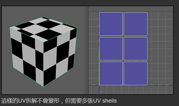
查看LightmapChart:
Scene -> Draw Mode -> GI -> UV Chart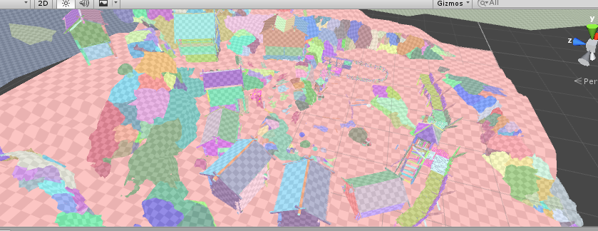
查看特定物件的UV Chart:
- 选中要查看的物体
- Window -> Lighting -> Obejct
- 左上角选择Chart模式
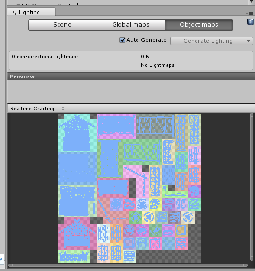
Charting模式的预览视窗会用不同的颜色的格子表示光照图,并用浅蓝色的线表示UV贴图。
更多关于UV Chart生成相关的因素,参考:
Unwrapping and Chart reduction
这里简单提一下:
Mesh Renderer上面的:
- Auto UV Max Distance(自動最大UV距離)
- Auto UV Max Angle(自動最大UV角度)
- Preserve UVs(保留UV)
- Ignore Normals(忽略法線)
开启Auto Lighting,然后调节相关数值通过UV Chart Preview帮助我们快速查看UV Chart实时效果。
如何通过UV Chats判定失真程度?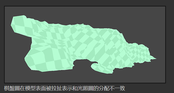
当启用UI Charts绘制模式时,失真的程度能从场景里的棋盘圆拉扯状况来评估。
如何正确使用Probe Lighting减少Static物体参与PRGI?
Probe lighting is a fast technique for approximating lighting in realtime rendering applications such as games.(光照探测技术是一个能在游戏里让即时光照更逼真的快速演算法)
原理:
Probe lighting works by sampling the incoming lighting at a specific point in 3D space and encoding this information across a sphere using mathematical functions known as spherical harmonics. These coefficients have low storage cost and can be then be quickly ‘unpacked’ at gameplay and used by shaders within the Scene to approximate surface lighting.(光照探测的原理是透过放在3D空间里的探针来接受照明信息,然后用像球鞋函数(spherical harmonics)的数学算法将结果编码在一个球体上,这些信息暂用空间很小,但在游戏运行时解包很快,并参与表面光照计算)
Note:
我們的目的是取样场景里的间接或反射光照。为了让每个光照探头效能花在刀口上, 尽量确保他们对一些变化明显的地方进行采样
如何减少Cluster数量?
让我们先通过查看贴图了解下Cluster真实情况: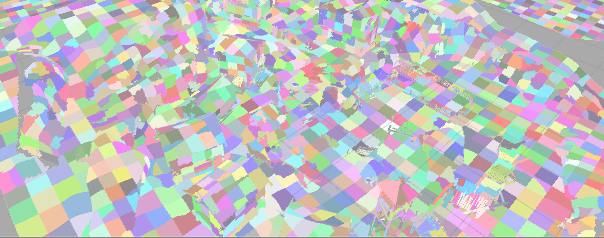
Clusters sample the albedo of the Static geometry to which they are mapped. Then, during the Light Transport stage of the precompute, the relationship between these Clusters is calculated so that light can be propagated throughout the Cluster network.
(Cluster会对静态物体表面的反射率(Albedo)进行采样,在光照传递计算阶段计算Cluster之间的关系好让光在整个Cluster网之间传递)
一旦与计算完成后,你就可以修改Skybox或光线的位置,强度和颜色,不需要重新与计算,光线就会透过这些Cluster网信息,联通场景材质和发光材质一并考虑计算光照反射。
Clustering或Lit Clustering Scene Mode模式来观察Cluster分布
了解了Cluster相关知识概念后,那么如何真正降低Cluster数量了?
Lightmap Parameters控制,用于公用。
Asset > Create > Lightmap Parameters
通过GameObejct -> Mesh Renderer -> Lightmao Parameters指定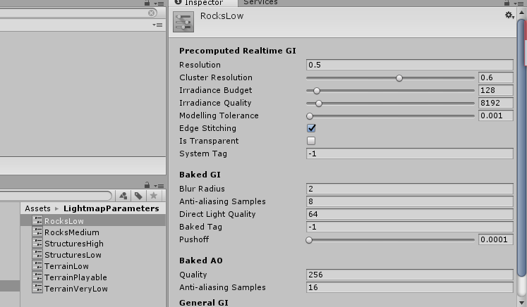
具体参数详细学习参考:
Unity預計算即時GI - 8.微調光照參數
PRGI实战:
- 设置需要Bake的物体为Static(规划好层级可快速批量设置Static)
- Window -> Lighting -> Build(勾选Auto,自动触发Precompute)
- 减少Lightmap Chart数量(部分物体(比如凸起的小物件)用Lighting Probe技术而非Static)
- 管理Lighting Probe(创建GameObject > Light > Light Probe Group)
- 放置Lighting Probe(GameObject > Light > Light Probe Group -> Edit Light Probes)
Baked Lighting AssetBundle实战:
目标:
- Baked Lighting,通过打包AB的形式加载还原Baked Lighting
- 支持Reflection Probe的AB加载还原(这个只是单纯加载了依赖的Cubemap没有做任何的还原操作,暂时表现是对的,具体待学习了解)
实战:
- 新建一个场景,添加必要的物件与光照
- 设置需要Bake的物体为Static
- 减少Lightmap Chart数量(部分物体(比如凸起的小物件)用Lighting Probe技术而非Static)
- 设置所有需要参与Bake的光照为Baked模式(只用于Baked Lighting)
- Window -> Lighting -> Build(勾选Auto,自动触发Precompute Lightmap)
- 删除所有完成静态烘焙的Light
- 记录场景里所使用的光照信息(LightmapSettings.lightmaps)以及所有参与了静态光照的静态物体所使用的光照图信息(Renderer.lightmapIndex和Renderer.lightmapScaleOffset)
- 运行时加载所有依赖的光照贴图信息,并还原所有静态物体使用的光照贴图信息
烘焙之后的场景光照使用信息: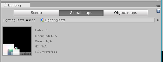
烘焙之后记录下场景使用的光照信息运行时还原:
打包场景AB以及光照信息记录代码:
1 | var sceneasset = AssetDatabase.LoadAssetAtPath<Object>(abfullpath); |
还原代码:
1 | using System.Collections; |
光照信息记录: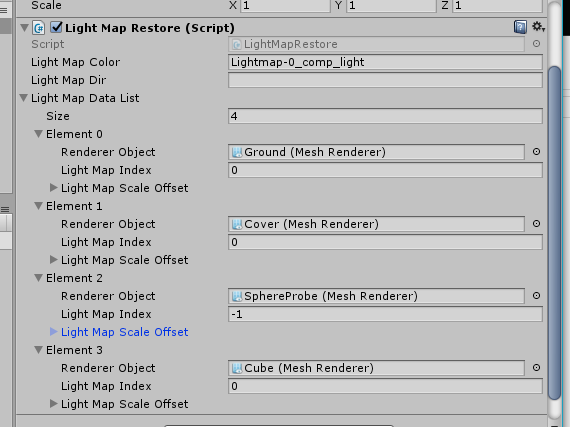
加载还原后的效果: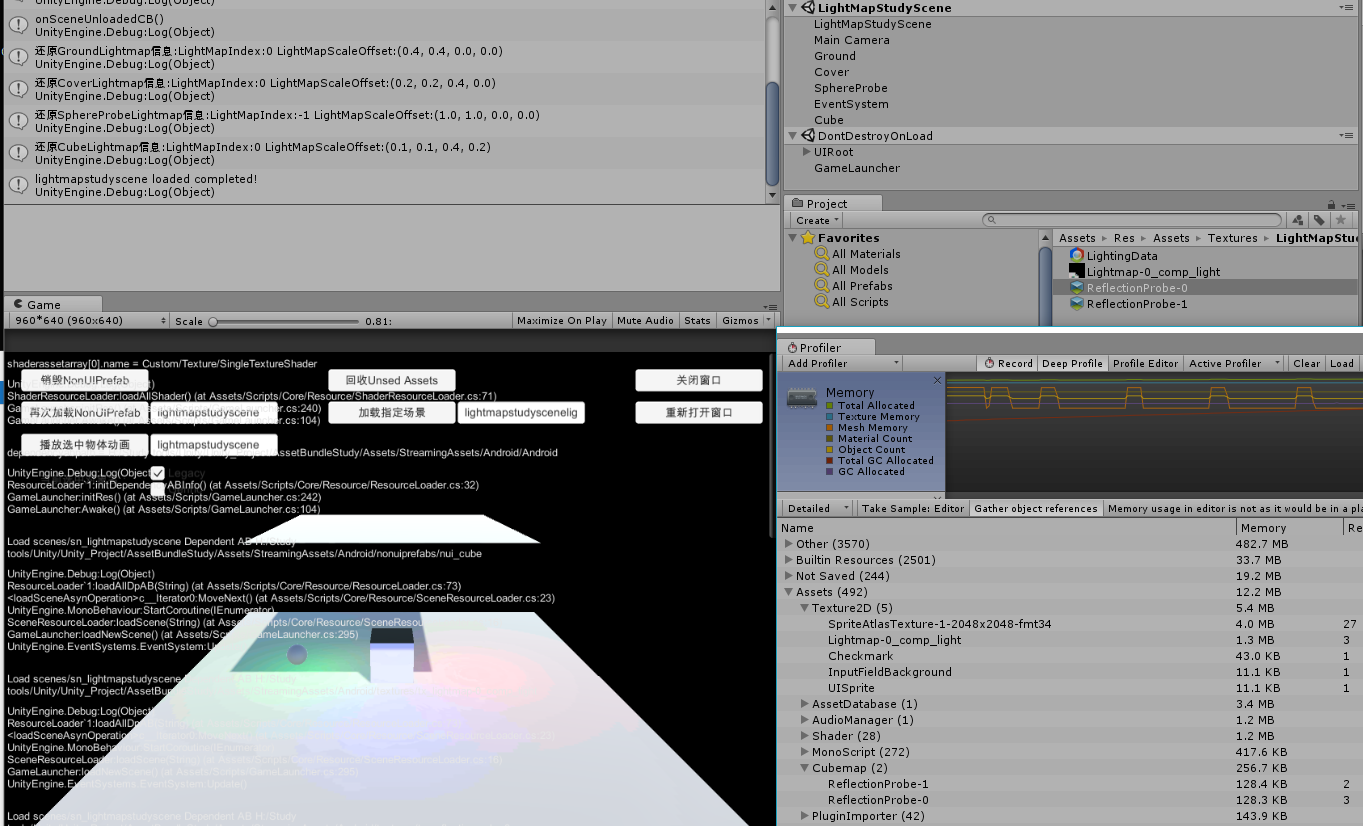
那如何Bake多份Lightmap进行动态切换了?
Unity 5.X如果想Bake多份Lightmap,需要复制保留之前Bake出的Texture,然后通过修改LightmapSetting的值即可(因为是同一个场景,静态物体的lightmapIndex和lightmapScaleOffset值都没变,所以直接切换LightmapSetting里的lightmaps即可)。
1 | var lightmaptex = TextureResourceLoader.getInstance().loadTexture(newlightmapname); |
参考文章:
Introduction to Precomputed Realtime GI
Unity預計算即時GI
Render Path
Forward Rendering
实时光照运算,计算量跟灯光数量成正比
Deffered Rendering
实时光照运算,计算量跟Pixels数量成正比而非光照
Edit -> Project Setting -> Player -> Rendering -> Rendering Path
Color Space
Linear Color Space
A significant advantage of using Linear space is that the colors supplied to shaders within your scene will brighten linearly as light intensities increase.
Gamma Color Space
Gamma’ Color Space, brightness will quickly begin to turn to white as values go up, which is detrimental to image quality.
Edit -> Project Setting -> Player -> Rendering -> Color Space
High Dynamic Range
HDR(High Dynamic Range) defines how extremely bright or dark colors are captured by scene cameras.(HDR决定光照颜色信息精度)
Note:
HDR is unsupported by some mobile hardware. It is also not supported in Forward Rendering when using techniques such as multi-sample anti-aliasing (MSAA).(Forward Rendering使用MSAA时不支持HDR)
待续
基础纹理
纹理类型分类
一下以Unity支持的导入设置纹理格式来分(一下只重点关注几个重要的):
Note:
随着Unity版本的变化,以下格式可能有细微变化(比如5.4里面的Adavanced已经没有了,取而代之的是细分到其他几个类型里)
Delfaut(Advanced)
这个是Unity在高版本默认的纹理格式,也是平时我们最常用的纹理格式之一。
如果要想将2D纹理图片作为纹理渲染到3D物体上,我们需要选择Default进行纹理格式的基本导入设置。
这里只提几个比较重要的设置,后续会讲到相关的概念。
- Non Power of 2(用于将不是2的倍数的纹理图片进行优化处理成2的倍数的宽高)
- Generate Mip Maps(预生成多个不同大小的纹理图片,用于不同距离是显示,解决很大的纹理在显示很小的时候失真和浪费的问题)
- Wrap Mode(用于设置处理在tiled纹理图片时的方式)
Normal Map
在之前的OpenGL学习中已经接触过Normal Map了,这里只是简单说一下什么是和为什么需要Normal Map。
至于什么是Bump Mapping,为什么normal map的normal值是存在tangent space,什么是tangent space,详情参考:
Normal Map
Sprite
这个是我们制作UI和2D游戏最常用的格式。
这里也将几个Sprite比较重要的设置:
- Packing Tag(Unity自带的打包图集工具所使用用于决定哪些图片时打在同一个图集里的标识。采用TexturePacker单独处理图片格式以及图集见后面)
- Pixels Per Unit(用于决定图片在屏幕上的映射显示大小,这个以及Camera Orthographic Size会影响我们制作Sprite时的大小标准以及Pixel Perfect显示。详情参考之前的学习Unity Unit & Pixel Per Unit和NGUI 2.7屏幕自适应)
- Generate Mip Maps(这个概念和前面Default提到的一样,但大部分时候UI和2D游戏都不需要设置这个,因为UI一般不会有太大的大小变化,2D游戏里的图片同理)
Lightmap
待学习
更多的纹理格式还有Editor GUI and Legacy, Cursor, Cookier, Single Channel这里就不一一详解了,详情参见[TextureTypes]](https://docs.unity3d.com/Manual/TextureTypes.html)
纹理大小
上面是Unity官方给出的建议,Texture纹理大小宽高最好是2的N次方倍数。
那么为什么会有Power Of 2这个原则了?
- 硬件GPU(以前的GPU还不支持Non Power Of 2大小的Texture加载。现在虽然支持了但Power Of 2的加载速度始终要比Non Power Of 2快)
- 内存使用(None Power Of 2的Texture在分配内存时始终会分配最近的Power Of 2大小,如果不采用Power Of 2的Texture会浪费部分内存分配)
- 纹理压缩格式支持(有些纹理压缩格式只支持特定宽高的纹理图片,比如DXT1只支持mutilple of 4的Texture Size压缩)
Texture的最大Size受限于渲染API(相当于硬件所支持的API)等级有关: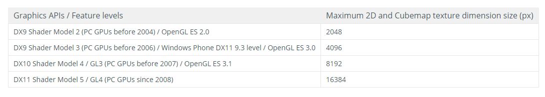
Note:
如果我们想在Unity里使用Non Power Of 2的Texture,我们需要在导入Texture时手动设置成NPO2,不然Unity会自动帮我们转换成Power Of 2的Texture。
参考文章:
OpenGL* Performance Tips: Power of Two Textures Have Better Performance
图片格式
图片是游戏里使用最基础也是最频繁的资源,图片的格式是决定内存占用多少的关键。
所以这里需要了解为什么图片格式会影响最终的内存占用以及如何选择正确的图片格式达到最低的内存占用实现我们所需的效果。以及相关工具帮助我们优化图片内存占用的问题。
图片加载内存计算方式?
图片宽度 * 图片高度 * 每个像素点的位数 = 内存大小
图片格式决定了每个像素点的位数的多少,比如RGBA8888(32-bit图)代表每个像素点存储了8 bit的R,G,B,A(分别代表红绿蓝透明通道),总共32 bit即4 byte大小。
所以1024 * 1024大小的RGBA8888的图片所需内存占用计算如下:
1024 * 1024 * 4byte = 4M
图片格式有哪些?
以下引用至图片格式及内存占用:
(1)RGBA8888(32-bit)
RGBA 4个通道各占8位,如果想获得最好的图片质量,使用这种格式最靠谱,但他占用的内存会比16位的纹理多一倍,加载速度相对较慢。
(2)RGBA4444(16-bit)
RGBA 4个通道各占4位,他对每个通道都有不错的支持,还能保证相对良好的图片质量,以及加载速度和内存占用。
(3)RGB5A1 (16-bit)
RGB 3个通道各占5位,A通道仅占一位,RGB通道表现良好,A通道只有透明和不透明两种,加载速度和内存占用表现良好。
(4)RGB565 (16-bit)
RGB 3个通道分别占5、6、5位,没有A通道,在16为纹理中,图片质量最好。
如何选择正确的图片格式?
了解各个图片格式的详细信息后,图片格式的选取根据具体需求而定。取舍主要在于内存占用和显示质量。待深入度研究。
参考文章:
图片格式及内存占用
纹理压缩方式
从上述官网描述可以看出,我们游戏最终使用的纹理格式并非最初我们导入的JPG,PNG,PSD or TGA,而是经过特定压缩方式(ETC,PVRTC,ATC,DXT……)压缩后的指定纹理格式的Texture,目的是为了运行使用Texture时更高效,内存占用和显示质量上可以做取舍。
各平台主流通用的纹理压缩方式:
PC – DXT
Android – ETC
IOS – PVRTC
Unity纹理使用
下面是个人总结的部分知识点:
Unity最终使用的不是我们最初导入到项目工程里的JPG,PNG等,而是通过根据指定压缩方式(e.g. ETC)得到的特定纹理格式(e.g. RGBA8888)的纹理图片,目的是为了减少内存开销以及加快GPU的纹理采样速度。
如何选择正确的纹理格式?
了解各个纹理格式的详细信息后,纹理格式的选取根据具体需求而定。取舍主要在于内存占用和显示质量之间。
那么有什么相关工具可以帮助我们优化图片使用过程中的内存占用问题吗?
答案是:SpritePacker(Unity官方自带工具,最新的Unity 2017貌似推出了Sprite Atlas,打包图集更加灵活) 和 TexturePacker(第三方工具,打包图集(优化空白处减少内存开销,指定图集导出格式减少内存占用,减少drawcall等好处))
那么使用哪一个(Sprite Packer or Texture Packer)用于Unity图集打包工具更好了?
Unity通过SpritePacker模糊了图集的概念,通过Sprite Packer设置Tag打包的图集只有在最后打包的时候才会被打进包里。Sprite Packer虽然与Unity开发结合的比较紧密,但灵活度上有所欠缺,Unity 2017推出的Sprite Atlas在灵活度上加强了不少。
TexturePacker作为第三方工具,结合Unity使用灵活度更高,可以自定义图集打包的各项参数等,最终放到Unity里的图集是已经打包好的图集。
就当前5.4版本的Unity而言,在没有Sprite Altas的前提下,个人觉得采用Texture Packer会更灵活一些,通过Texture Packer我们可以预先打出图集,然后直接将图集打包成ab。
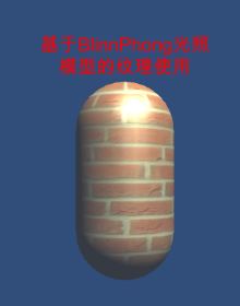
纹理的基础使用
纹理最基础的应用是用于模型外观。
我们直接来看看BlinnPhong光照模型结合纹理贴图的使用代码:
1 | // Upgrade NOTE: replaced '_Object2World' with 'unity_ObjectToWorld' |
Mipmap
说到纹理的使用,这里不得不提的就是Mipmap的应用:
mipmap主要是由于物体在场景中因为距离的缘故会在屏幕显示的大小有变化,如果我们在物体很远,只需要显示很小一块的时候还依然采用很大的纹理贴图,最终显示在屏幕上的纹理会很不清晰(失真)。为了解决这个问题,mipmap应运而生,通过事先生成或指定多个级别的同一纹理贴图,然后在程序运作的过程中通过计算算出应该使用哪一个等级的纹理贴图来避免大纹理小色块失真的问题。
在Unity为Texture开启Mipmap,我们需要把纹理类型设置成Advanced,然后勾选Generate Mip Map即可: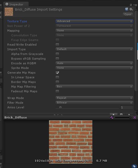
需要注意的是,Unity开启Mipmap后会导致资源纹理内存占用增加。关于Advanced纹理的各个详细参数信息参考Texture Import Setting
Note:
注意纹理在DX和OpenGL里的起点不一样,DX是左上角(0,0),OpenGL和Unity是左下角(0,0)。
凹凸映射
这里的凹凸映射指的就是之前OpenGL学习的Normal Mapping和Bump Mapping,这里直接使用之前的总结:高模normal map用于低模模型上,即不增加渲染负担又能增加渲染细节。
还有一个凹凸映射叫做高度纹理(Height Map),一般用于存储地形高度信息。
Height Map
用于存储高度信息,通常用于地形的Height Map。
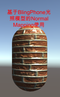
Normal Mapping
关于Normal Mapping要注意的地方主要是两点:
- 存储的法线信息是基于切线空间的,需要转换计算位于世界坐标系的法线信息。
- 纹理贴图的信息范围是[0,1],而法线信息时[-1,1]需要通过映射转换。
这里直接给出使用Unity编写Normal Mapping的使用代码和效果(以下代码采用的是将切线空间的法线转换到世界坐标系参与光照计算的方法):
1 | // Upgrade NOTE: replaced '_Object2World' with 'unity_ObjectToWorld' |
Ramp Texture(渐变纹理)
比较普遍的用法是使用渐变纹理来控制漫反射光照运算。
让我们直接看代码和效果图。
1 | Shader "Custom/Texture/RampTextureShader" |
可以看出利用半兰伯特把法线映射到[0,1]后,作为渐变纹理采样的uv,这样一来面向光照方向的顶点会更靠纹理采样的1,反之完全与光照相反方向的顶点会更靠近纹理采样的0的位置,然后把渐变纹理的采样信息作为漫反射的基础颜色信息参与光照运算。
Mask Texture(遮罩纹理)
“遮罩允许我们可以保护某些区域,使它们免于修改。遮罩纹理已经不止限于保护区域避免修改,而是存储我们希望逐像素控制的表面属性。”
让我们直接看代码和效果图:
1 | // Upgrade NOTE: replaced '_Object2World' with 'unity_ObjectToWorld' |
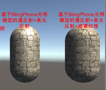
可以看到我们利用遮罩纹理的R颜色信息作为高光的过滤依据,也就是说遮罩纹理里R信息为0的顶点将不会计算高光反射。
透明效果
Reference Website
Surface shaders in Unity3D
[Unity Shader内置文件官网下载地址](http://unity3d.com/cn/get-unity/download/
archive)
Shader semantics官网查询
Unity Shader入门精要勘误
Unity Shader入门级你要源代码
Gouraud Shading
