OpenGL学习
- 1. OpenGL
- 2. Wavefront OBJ exported by MilkShape 3D
- 3. 762 vertices
- 4. 302 texture coordinates
- 5. 747 normals
- 6. 80 triangles in group
- 7. 1368 triangles total
- 7.1. OpenGL learning journal
- 7.2. OpenGL Practice
- 7.2.1. Check supported OpenGL version
- 7.2.2. Know what Glut and Glew are, and how to use them
- 7.2.3. Open a Window
- 7.2.4. Using OpenGL
- 7.2.5. Using Shader
- 7.2.6. Uniform Variables
- 7.2.7. Interpolation
- 7.2.8. Coordinate Transformations & Perspective Projection
- 7.2.9. Keyboard && Mouse Control
- 7.2.10. Texture Mapping
- 7.2.11. Light and Shadow
- 7.2.12. Skybox
- 7.2.13. Normal Mapping
- 7.2.14. BillBoard And Geometry Shader
- 7.2.15. 3D Picking
- 7.2.16. Basic Tessellation
- 7.2.17. Vertex Array Objects
- 7.2.18. Instanced Rendering
- 7.2.19. GLFX - An OpenGL Effect Library
- 7.2.20. Deferred Shading
- 7.3. OpenGL Utility
- 8. Reference Website:
时隔将近一年了,再次拾起了还未学完的OpenGL,这一年工作生活学习状态都不好,希望这一次能重新好好的把OpenGL学好,把图形渲染的基础知识掌握好 – 游戏梦
参考书籍:
《OpenGL Programming Guide 8th Edition》 – Addison Wesley
《Fundamentals of Computer Graphics (3rd Edition)》 – Peter Shirley, Steve Marschnner
《Real-Time Rendering, Third Edition》 – Tomas Akenine-Moller, Eric Haines, Naty Hoffman
OpenGL
Introdction to OpenGL
What is OpenGL?
- OpenGL is an application programming interface – “API” for short – which is merely a software library for accessing features in graphics hardware.(访问图形硬件设备功能的API)
- OpenGL is a “C” language library(OpenGL是一个C语言库)
History
It was first developed at Silicon Graphics Computer Systems with Version 1,0 released in July of 1994(wiki)
Next Generation OpenGL
OpenGL relative knowledge
OpenGL render pipeline
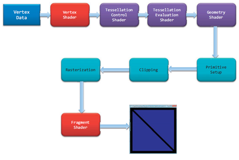
Vertex Data
Sending Data to OpenGLVertex Shader
Process the data associated with that vertexTessellation Shader
Tessellation uses patchs to describe an object’s shape, and allows relatively simple collections of patch geometry to be tessellated to increase the number of geometric primitives providing better-looking models (eg: LOD)Geometry Shader
Allows additional processing of individual geometric primitives, including creating new ones, before rasterizationPrimitive Assembly
Organizes the vertices into their associated geometric primitives in preparation for clipping and rasterizationClipping
Clip the vertex and pixels are outside of the viewport – this operation is handled automatically by OpenGLRasterization
Fragment generation. Pixels have a home in the framebuffer, while a fragment still can be rejected and never update its associated pixel location.Fragment Shading
Use a fragment shading to determine the fragment’s final color, and potentially its depth valuePer-Fragment Operations
If a fragment successfully makes it through all of the enabled tests (eg: depth testing, stencil testing), it may be written directly to the framebuffer, updating the color of its pixel, or if blending is enabled, the fragment’s color will be combined with the pixel’s current color to generate a new color that is written into the framebuffer
Note:
Fragment’s visibility is determined using depth testing and stencil testing
Pixel data is usually stored in texture map for use with texture mapping, which allows any texture stage to look up data values from one or more texture maps.
OpenGL Shader Language (GLSL)
GLSL - OpenGL Shading Language 也称作 GLslang,是一个以C语言为基础的高阶着色语言。它是由 OpenGL ARB 所建立,提供开发者对绘图管线更多的直接控制,而无需使用汇编语言或硬件规格语言。
编译和执行
GLSL 着色器不是独立的应用程式;其需要使用 OpenGL API 的应用程式。C、C++、C#、Delphi 和 Java 皆支援 OpenGL API,且支援 OpenGL 着色语言。
GLSL 着色器本身只是简单的字串集,这些字串集会传送到硬件厂商的驱动程式,并从程式内部的 OpenGL API 进入点编译。着色器可从程式内部或读入纯文字档来即时建立,但必须以字串形式传送到驱动程式。
工具
GLSL 着色器可以事先建立和测试,现有以下 GLSL 开发工具:
RenderMonkey - 这个软件是由 ATI 制作的,提供界面用以建立、编译和除错 GLSL 着色器,和 DirectX 着色器一样。仅能在 Windows 平台上执行。
GLSLEditorSample - 在 Mac OS X 上,它是目前唯一可用的程式,其提供着色器的建立和编译,但不能除错。它是 cocoa 应用程式,仅能在 Mac OS X 上执行。
Lumina - Lumina 是新的 GLSL 开发工具。其使用 QT 界面,可以跨平台。
The color space in OpenGL
In OpenGL, colors are represented in what’s called the RGB color space
.obj and .mtl file format
参考文章:
obj文件基本结构及读取 - 计算机图形学
3D模型-OBJ材质文件 MTL格式分析
.mtl文件格式解析 - [建模]
“OBJ文件不包含面的颜色定义信息,不过可以引用材质库,材质库信息储存在一个后缀是”.mtl”的独立文件中。关键字”mtllib”即材质库的意思。 材质库中包含材质的漫射(diffuse),环境(ambient),光泽(specular)的RGB(红绿蓝)的定义值,以及反射(specularity),折射(refraction),透明度(transparency)等其它特征。 “usemtl”指定了材质之后,以后的面都是使用这一材质,直到遇到下一个”usemtl”来指定新的材质。”
.obj的一些基本内容格式描述:
‘#’ 这个就相当于C++代码里面的//,如果一行开始时#,那么就可以理解为这一行完全是注释,解析的时候可以无视
g 这个应该是geometry的缩写,代表一个网格,后面的是网格的名字。

v v是Vertex的缩写,很简单,代表一个顶点的局部坐标系中的坐标,可以有三个到四个分量。我之分析了三个分量,因为对于正常的三角形的网格来说,第四个分量是1,可以作为默认情况忽略。如果不是1,那可能这个顶点是自由曲面的参数顶点,这个我们这里就不分析了,因为大部分的程序都是用三角形的。

vn 这个是Vertex Normal,就是代表法线,这些向量都是单位的,我们可以默认为生成这个obj文件的软件帮我们做了单位化。

vt  这个是Vertex Texture Coordinate,就是纹理坐标了,一般是两个,当然也可能是一个或者三个,这里我之分析两个的情况。

mtllib <matFileName> 这个代表后面的名字是一个材质描述文件的名字,可以根据后面的名字去找相应的文件然后解析材质。

usemtl <matName> 这里是说应用名字为matName的材质,后面所有描述的面都是用这个材质,直到下一个usemtl。

f 这里就是face了,真正描述面的关键字。后面会跟一些索引。一般索引的数量是三个,也可能是四个(OpenGL里面可以直接渲染四边形,Dx的话只能分成两个三角形来渲染了)。每个索引数据中可能会有顶点索引,法线索引,纹理坐标索引,以/分隔。
.mtl文件(Material Library File)是材质库文件,描述的是物体的材质信息,ASCII存储,任何文本编辑器可以将其打开和编辑。一个.mtl文件可以包含一个或多个材质定义,对于每个材质都有其颜色,纹理和反射贴图的描述,应用于物体的表面和顶点。”
.mtl的一些基本内容格式描述:
以下是一个材质库文件的基本结构:
newmtl mymtl_1
材质颜色光照定义
纹理贴图定义
反射贴图定义
……

注释:每个材质库可含多个材质定义,每个材质都有一个材质名。用newmtl mtlName来定义一个材质。对于每个材质,可定义它的颜色光照纹理反射等描述特征。主要的定义格式如下文所示:

////////////////////////////////////////////////
材质颜色光照
1。环境反射有以下三种描述格式,三者是互斥的,不能同时使用。
Ka r g b ——用RGB颜色值来表示,g和b两参数是可选的,如果只指定了r的值,则g和b的值都等于r的值。三个参数一般取值范围为0.0~1.0,在此范围外的值则相应的增加或减少反射率;
Ka spectral file.rfl factor ——用一个rfl文件来表示。factor是一个可选参数,表示.rfl文件中值的乘数,默认为1.0;
Ka xyz x y z ——用CIEXYZ值来表示,x,y,z是CIEXYZ颜色空间的各分量值。y和z两参数是可选的,如果只指定了x的值,则y和z的值都等于r的值。三个参数一般取值范围为0~1。

2。漫反射描述的三种格式:
Kd r g b
Kd spectral file.rfl factor
Kd xyz x y z

3。镜反射描述的三种格式:
Ks r g b
Ks spectral file.rfl factor
Ks xyz x y z

4。滤光透射率描述的三种格式:
Tf r g b
Tf spectral file.rfl factor
Tf xyz x y z

5。光照模型描述格式:

illum illum_#
指定材质的光照模型。illum后面可接0~10范围内的数字参数。各个参数代表的光照模
从上面的内容可以看出,.obj是描述关于顶点,法线,面,纹理坐标和材质引用等相关的数据的集合,而.mtl是用于定义实际材质信息的文件。
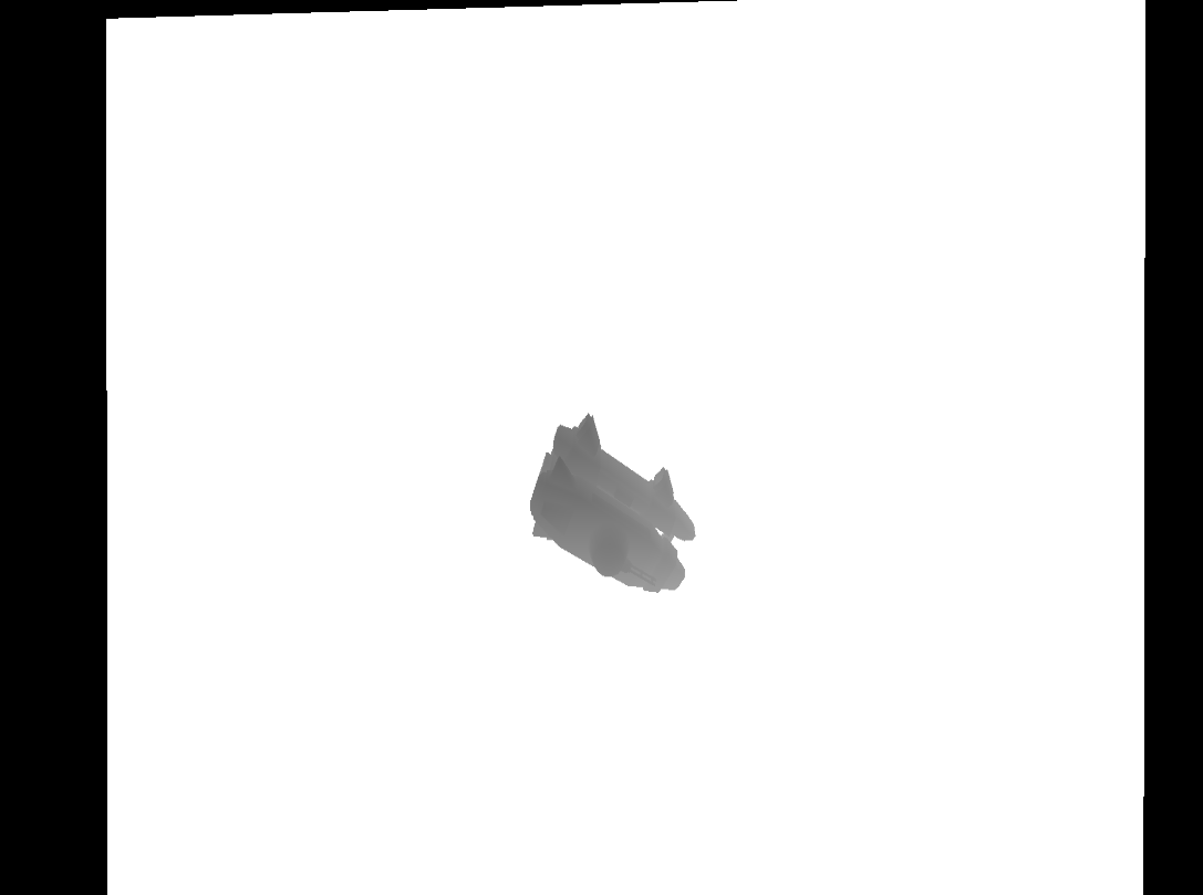
了解了.obj和.mtl文件里面的内容描述方式,让我们来看看在实际中.obj和.mtl文件内容来学习理解一下,以下内容来源于Modern OpenGL Tutorials – 3D Picking 的spider.obj和spider.mtl```CPP
spider.obj
Wavefront OBJ exported by MilkShape 3D
mtllib spider.mtl
v 1.160379 4.512684 6.449167
…..
762 vertices
vt 0.186192 0.222718
…..
302 texture coordinates
vn -0.537588 -0.071798 0.840146
……
747 normals
g HLeib01
usemtl HLeibTex
s 1
f 1/1/1 2/2/2 3/3/3
……
80 triangles in group
……
1368 triangles total
1 | 从第二行mtllib spider.mtl可以看出spider.obj指定了纹理材质的描述文件是spider.mtl。 |
第五行newmtl Skin定义了一个材质的名字,后面Ka, Kd, Ks, Ns, map_Kd分别是对该材质的环境反射,漫反射,镜面反射,高光系数,纹理图片的配置。
综合上述的理解,可以看出,当我们通过assimp引用加载spider.obj这个文件的时候,我们会去使用spider.mtl作为材质配置文件去作为读取到的材质相关的信息,从而我们知道了我们需要spider.obj,spider.mtl,wal67ar_small.jpg,wal69ar_small.jpg,SpiderTex.jpg,drkwood2.jpg,engineflare1.jpg这些文件提供我们完整的mesh渲染相关的数据。
OpenGL learning journal
API
查看哪些错误标志位被设置
了解:
OpenGL在内部保留了一组错误标志位(共4个),其中每一个标志位代表一种不同类型的错误。当错误一个发生时,与这个错误对应的标志就会被设置。如果被设置的标志不止一个,glGetError仍然只返回一个唯一的值。当glGetError函数被调用时,这个值随后被清除,然后在glGetError再次被调用时将返回一个错误标志或GL_NO_ERROR为止
函数:
Glenum glGetError(void);查询OpenGL的渲染引擎(OpenGL驱动程序)的生产商和版本号
了解:
OpenGL允许提供商通过它的扩展机制进行创新。为了使用特定供应商所提供的一些特定扩展功能,我们希望限制这个特定供应商所提供驱动程序的最低版本号。
函数:
const Glubyte *glGetString(GLenum name);设置和查询管线的状态
了解:
OpenGL使用状态模型来跟踪所有的OpenGL状态变量来实现对OpenGL渲染状态的控制
函数:
void glEnable(GLenum capability);
void glDisable(GLenum capability);
void glGet*(Type)v(GLenum pname, GLboolean *params);查询program的一些相关信息和一些错误信息
了解:
OpenGL的pragram链接可能由于GLSL里面的一些错误导致出错,我们需要知道关于program object的一些相关错误信息,同时我们也想知道我们现有的program相关的一些信息
函数:
void glGetProgramiv(GLuint program, GLenum pname, GLint *params);得到shader链接出错的log信息
了解:
OpenGL的shader object可能链接失败,我们需要知道shader里面出错的信息
函数:
void glGetProgramInfoLog(GLuint program, GLsizei maxLength, GLsizei *length, GLchar *infoLog);
注意:
可以通过glGetProgramiv()去得到program的一些log相关信息,比如GL_INFO_LOG_LENGTH
OpenGL Knowledge:
“OpenGL Execute Model:
The model for interpretation of OpenGL commands is client-server. An application (the client) issues commands, which are interpreted and processed by OpenGL (the server). The server may or may not operate on the same computer as the client. In this sense, OpenGL is network-transparent. ““client-server 模式:
OpenGL 是一种 client-server 模式,当你的应用程序调用 OpenGL 函数时, 它将告诉OpenGL client, 然后 client 将渲染命令传送给 server. 这里client 和 server可能是不同的计算机,或是同一台计算机上的不同进程。一般来说 server 是在 GPU上处理的, 而 client 是在 CPU 上处理的,这样分担了 CPU 的负担, 同时高效利用了GPU.”
但如果Client和Server没在同一个机器上,我们就需要一种一种网络传输协议框架来实现他们之间的交流:
X Window System
但X Window System里的client和server与传统的C/S模式相反,client是负责运算的,server是负责显示的。
但OpenGL的client和server的交流原理是与X Window System相似的
OpenGL Practice
Check supported OpenGL version
- Install the appropriate graphic driver which enables usage of the functionality provided.
check the graphic drive update.(更新显卡驱动获得最新的OpenGL版本支持) - Using OpenGL extensions viewer to check which OpenGL version is supported(查看当前硬件所支持的OpenGL版本)
download website
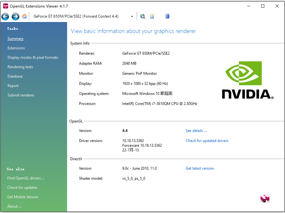
从上图可以看出我当前的电脑和显卡驱动支持最高4.4,所以在使用学习OpenGL之前一定要确认好自己电脑所能支持的版本,避免后续不必要的问题。
检查完所支持的OpenGL版本后,下面我们需要介绍两个在学习OpenGL时为了帮助快速学习使用OpenGL的两个重要库(Glut & Glew)
Know what Glut and Glew are, and how to use them
Glut (OpenGL Utility Toolkit)
GLUT(英文全写:OpenGL Utility Toolkit)是一个处理OpenGL程式的工具库,负责处理和底层操作系统的呼叫以及I/O,并包括了以下常见的功能:- 定义以及控制视窗
- 侦测并处理键盘及鼠标的事件
- 以一个函数呼叫绘制某些常用的立体图形,例如长方体、球、以及犹他茶壶(实心或只有骨架,如glutWireTeapot())
- 提供了简单选单列的实现
GLUT是由Mark J. Kilgard在Silicon Graphics工作时所写,此人同时也是OpenGL Programming for the X Window System以及The Cg Tutorial: The Definitive Guide to Programmable Real-Time Graphics两书的作者。
GLUT的两个主要目的是建立一个跨平台的函式库(事实上GLUT就是跨平台的),以及简化学习OpenGL的条件。透过GLUT编写OpenGL通常只需要增加几行额外GLUT的程式码,而且不需要知道每个不同操作系统处理视窗的API。
所有的GLUT函数都以glut作为开头,例如glutPostRedisplay()。
Glew ( OpenGL Extension Wrangler Library)
The OpenGL Extension Wrangler Library (GLEW) is a cross-platform C/C++ library that helps in querying and loading OpenGL extensions. GLEW provides efficient run-time mechanisms for determining which OpenGL extensions are supported on the target platform. All OpenGL extensions are exposed in a single header file, which is machine-generated from the official extension list.(Glew是一个支持跨平台的C/C++库,用于运行时鉴别OpenGL扩展所支持的版本)
more info for extention toolsHow to use Glu & Glew?
- add glu.lib & glew.lib into additional dependencies
- add the directory that includes glu.h & glew.h into include dirctory
- Include GL/freeglut.h & GL/glew.h in source file
Note:
if you use static link, #define FREEGLUT_STATIC before you include GL/freeglut.h, otherwise it will look for freeglut.lib. #define GLEW_STATIC for Glew.
include GL/glew.h before GL/freeglut.h, otherwise, it will through “fatal error C1189: #error : gl.h included before glew.h”
Note:
后续的学习都是基于Modern OpenGL Tutorials,后续提到的一些库的源码从该网站下载
Open a Window
IncludeFiles.h
1 |
|
OpenGLWindow.h
1 |
|
final result:
从上面可以看出我们主要是通过调用glut来初始化创建windows窗口
通过glut里的API我们可以去设置回调,去实现我们在渲染时期需要设置的OpenGL状态
上述主要有四个重要的glut API:
- glutInitDisplayMode(GLUT_DOUBLE | GLUT_RGBA) – GLUT_DOULBE开启了双buffer渲染,这样效率更高,一个buffer用于渲染,一个buffer用于填充下一帧数据
- glutDisplayFunc – 设置glut里的渲染回调
- glutMainLoop – 开启glut里的window event监听
- glutCreateWindow – 设定完相关参数后,通过此方法我们能够创建出我们想要的Windows窗口,同时OpenGL Context也在这时候被创建出来
Glut还提供了更多的关于Window的功能,后续会学习使用到
Using OpenGL
上一章节只是用到了glut去初始化我们最基本的Window窗口,还没真正大量用到OpenGL里API,在使用OpenGL API之前我们需要通过Glew这个工具去检查当前所支持的OpenGL版本,然后才能正确的调用对应的API。
使用Glew的准备工作在How to use Glu & Glew?时已经提到,这里不重述了
因为Glew需要通过context去查找对应所支持的OpenGL版本调用,所以初始化Glew必须在创建OpenGL Context之后。
Note:
Call glewInit after glutCreateWindow call successfully
那这里就不得不先了解一下什么是OpenGL Context了?
“”OpenGL Context””
OpenGL context, which is essentially a state machine that stores all data related to the rendering of your application. When your application closes, the OpenGL context is destroyed and everything is cleaned up.
结合wikiCreating an OpenGL Context (WGL)的介绍,这里我理解的不是很清晰,大概是OpenGL的Context相当于Device Context(DC)相对于Windows的概念一样。Context会设定很多跟渲染相关的状态(比如是否使用双buffer,depthbuffer占多少字节,颜色模式,窗口大小等渲染需要的信息)
这里我们只需要知道初始化Glut和调用glutCreateWindow创建窗口后,我们的OpenGL Context就生成了.
这也就是为什么在初始化glew之前必须先初始化Glut和创建Windows窗口的原因。
进一步了解参考:
Creating an OpenGL Context (WGL)
Using Glew
接下来回到Glew的使用去绘制我们的第一个OpenGL圆点
IncludeFiles.h
1 |
|
UsingOpenGL.h
1 |
|
从上面可以看出,我们初始化glew只是调用了glewInit()方法,但主要一定要在OpenGL context创建完成后调用(即glutCreateWindow窗口创建之后)
我们创建并使用vertext buffer主要由5个步骤:
- glGenBuffers() – 创建一个可用的buffer obejct
- glBindBuffer() – 绑定buffer object到指定的target类型,target类型代表我们的buffer object包含什么样的数据用于什么样的用途
- glBufferData() – 填充buffer数据
- glVertexAttribPointer() – 指明如何去解析buffer里的数据,同时这里也指明了如何在shader里面访问这些数据(至于如何编写,编译,链接和使用Shader,后续会讲到。)
- glDrawArrays() – 调用draw指明如何使用并绘制buffer里面的数据
Note:
这里需要注意的一点,要想在Shader里访问buffer里面的attribute数据,我们需要在调用draw之前调用glEnableVertexAttribArray()来激活特定的attribute
final result:
Using Shader
上述是Wiki上Shader的定义。Shader是在可编程管线出现后,以程序的形式对渲染的各个阶段进行图形图像上的处理,使渲染变得更加灵活,主要作用于GPU上。
Shader作用于渲染的各个阶段:
之前在“Understand OpenGL render pipeline”有讲到各个渲染管线,这里就不再重述。可见Shader作用于大部分管线,比如:Vertex Shader(负责vertex数据处理),Tessellation Shader(负责以图形patch为单位的处理,用于描述物体形状数据,LOD就是在这个阶段实现的),Geometry Shader(以整个图形原件数据作为输入做处理,好比batch rendering可在这个阶段实现),Fragment Shading(以fragment(片元)数据作为输入做处理)
Shader Language在前面的“Understand OpenGL Shader Language”有讲到,这里就不重述了。
从上可见Shader在可编程管线的今天有着多么重要的作用。
接下来让我们看看在OpenGL中如何使用Shader吧。
使用Shader主要有下列几个步骤:
- Create a shader object – glCreateShader(GLenum type)(创建shader对象)
- Compile your shader source into the object – glShaderSource(******) glCompileShader(***)(编译shader文件,存储到shader对象中)
- Verify that your shader compiled successfully – glGetShaderInfoLog(***)(检查shader编译是否成功并获取错误信息)
- Create a shader program – glCreateProgram(void)(创建shader程序)
- Attach the appropriate shader objects to the shader program – glAttachShader(GLuint program, Gluint shader)(附加多个shader对象到shader程序中)
- Link the shader program – glLinkProgram(GLuint program)(链接shader程序)
- Verify that the shader link phase completed successfully – glGetProgramiv() & glGetProgramInfoLog(****)(检查shader程序链接是否成功并获取错误信息)
- Use the shader for vertex or fragment processing – glUseProgram(GLuint program)(使用shader程序做顶点处理或片元处理)
Shader出错后因为我们快速退出了程序,所以很难看到console的错误信息,所以最好的方式是把错误信息写入文本文件以供后续查看。Utils.h是关于编译和使用Shader并打印错误信息到文本的实现。
IncludeFiles.h
1 |
|
Utils.h
1 |
|
UsingShader.cpp
1 |
|
vsshader.vs
1 |
|
fsshader.fs
1 |
|
final effect: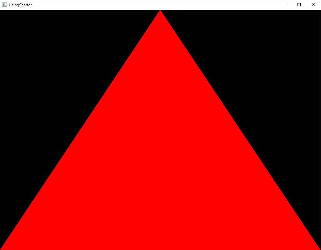
上述只使用到了Vertex Shader和Framgment Shader, 后续还会讲到其他Shader的使用。
Uniform Variables
Uniform variables are used to communicate with your vertex or fragment shader from “outside”.
从上面可以看出Uniform变量主要用于Vertex和Fragment Shader,并且对于所有传入的顶点值都不变,只能通过C++一侧去改变Uniform Variable的值。
接下来我们看看Uniform Variable是如何应用在Shader中的:
使用Uniform Variable主要有以下几个步骤:
- Obtain uniform variable location after Link Shader Program
1 | gScaleLocation = glGetUniformLocation(ShaderProgram, "gScale"); |
Set uniform variable value
1 | gScale += 0.01f; |
- Define uniform variable in Shader
1 |
|
final result: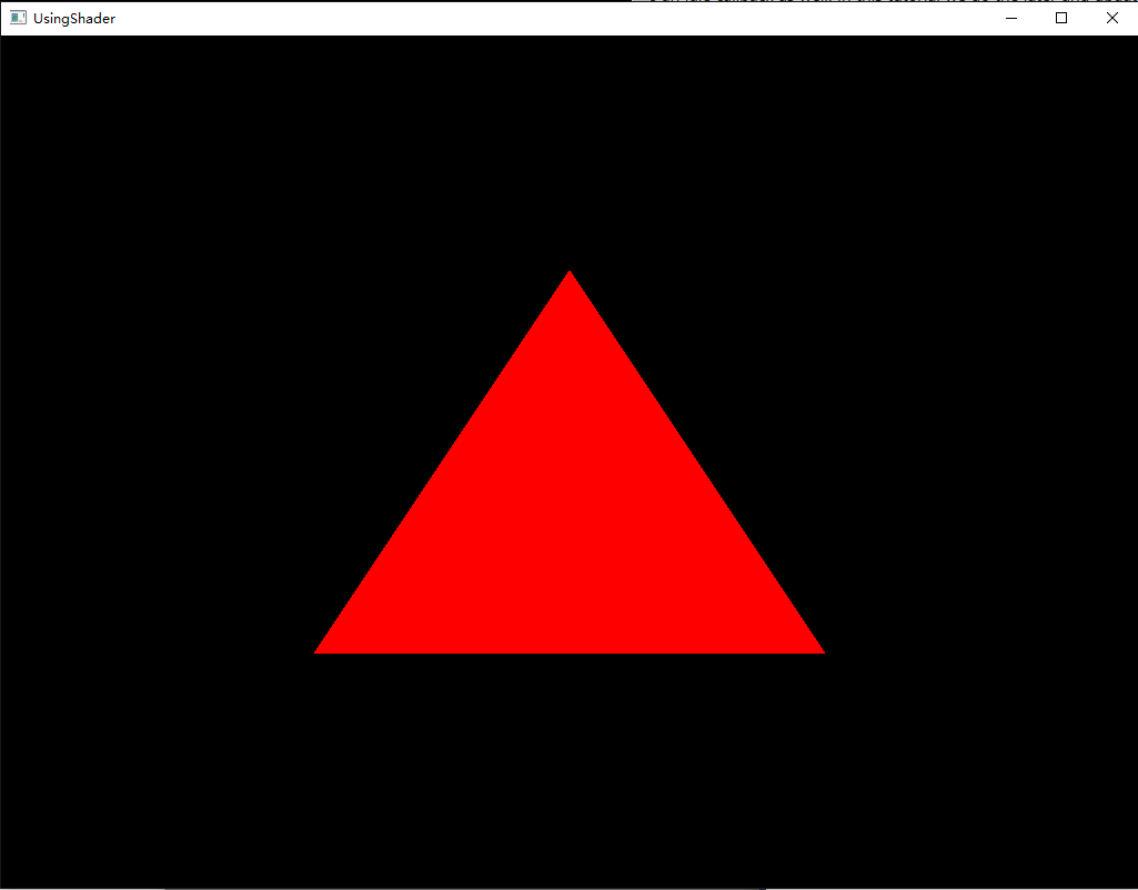
Interpolation
the interpolation that the rasterizer performs on variables that come out of the vertex shader.
在OpenGL的渲染管线里,在Fragment Shader执行之前会进行rasterizer,rasterizer会计算出各个三角形顶点之间的像素颜色数据,然后我们可以通过Fragment Shader对于光栅化的后颜色数据做进一步的处理。
这一章节主要看看我们是如何在Vertex Shader和Fragment Shader中如何对顶点数据和各像素信息做处理和数据传递的。(这里我们直接在VS中算出颜色信息直接传递到FS中去做处理)
要想从VS传递数据到FS,我们需要在Vertex Shader中定义关键词out的变量,并在Fragment Shader定义对应的关键词in的变量。
vsshader.vs
1 |
|
fsshader.fs
1 |
|
final result: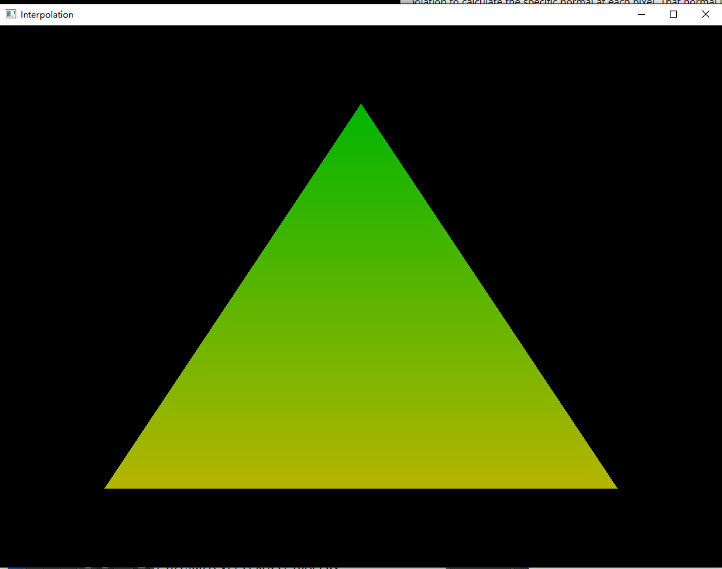
从上面可以看出在VS中算出颜色信息后,经过光栅化,三角形顶点之间的颜色信息被计算出来,最终传到FS中并作为最终颜色信息输出到屏幕上。
Coordinate Transformations & Perspective Projection
这一章主要是学习矩阵在3D图形中的使用和了解物体时怎样被显示到正确的屏幕位置的。
Note:
下列推导是基于OpenGL的列向量而非DX的行向量
在解释如何使用矩阵去进行向量变换之前,我们先来看看为什么矩阵可以实现向量变换?
下列学习参考《3D 数学基础:图形与游戏开发》
一个3维向量可以解释成3个基向量上平移后的组合(p,q,r为三个基向量):
V = x × p + y × q + z × r;
当一个向量乘以矩阵的时候:
1 | [ p ] [px py pz] |
“如果把矩阵的行解释为坐标系的基向量,那么乘以该矩阵就相当于执行了一次坐标系转换。若有a*M = b,我们就可以说,M将a转换到b。”
从上面我们可以看出矩阵是如何做到对于向量的坐标系转换的。
那么为什么我们后面用到的矩阵都是4×4而不是3×3的了?
44的矩阵我们叫做齐次矩阵。齐次矩阵出现的原因主要是除了记法方便,更重要的是因为33的变换矩阵只能表示线性变换,而4*4齐次矩阵能够表示线性变换和非线性变换。
那么这里我们来了解下什么是线性变换?
线性变换的满足下列公式:
F(a+b) = F(a) + F(b)
F(ka) = k × F(a)
因为线性变换不包含平移,所以这也是4×4齐次矩阵的出现的原因。
了解了使用矩阵的原因和为什么使用4×4齐次矩阵的原因后,让我们来看看,我们是如何通过矩阵来实现3D图形里的实现物体的坐标系变换的。
M(m-w) – 物体坐标系到世界坐标系
M(w-v) – 世界坐标系到观察坐标系
M(v-p) – 投影变换
V’ = V × M(m-w) × M(w-v) × M(v-p)
因为矩阵乘法满足结合律
N = M(m-w) × M(w-v) × M(v-p)
V’ = V × (M(m-w) × M(w-v) × M(v-p)) = V * N
所以我们只需要求出所有坐标系变换矩阵的乘积后再对V进行操作即可。
因为单个矩阵存储着一系列的变换,而这些变换可以通过多个单个变换组合而成,所以下列式子是成立的
M = S(scale) × R(rotation) × T(translation)
但这里有个比较关键的点,S,R,T直接的乘法顺序,矩阵是不满足交换律的,我们必须按S * R * T的顺序,原因参考下面:
One reason order is significant is that transformations like rotation and scaling are done with respect to the origin of the coordinate system. Scaling an object that is centered at the origin produces a different result than scaling an object that has been moved away from the origin. Similarly, rotating an object that is centered at the origin produces a different result than rotating an object that has been moved away from the origin.
从上面可以看出,之所必须按S * R * T的顺序是因为S和R都是针对坐标系原点进行的,一旦先执行T,那么相对于坐标系原点的位置就会有所变化,这之后再做S和R就会出现不一样的表现。
因为OpenGL是列向量是左乘,所以在OpenGL中顺序如下:
V’ = T × R × S × V
DX中顺序如下:
V’ = V × S × R × T
获取最终的M(m-w)的代码实现如下:
1 | const Matrix4f& Pipeline::GetWorldTrans() |
V’ = V × M(m-w) × M(w-v) × M(v-p)
我们知道了M(m-w)是如何计算出来的了,接下来我们要了解M(w-v) – 世界坐标系到观察坐标系
在了解如何从世界坐标系转换到观察坐标系之前我们先来看看摄像机的定义:
位置 – (x,y,z)
N – The vector from the camera to its target.(look at 朝向)
V – When standing upright this is the vector from your head to the sky.(垂直于N向上的向量)
U – This vector points from the camera to its “right” side”.(在N和V定了之后可以算出Camera的向右的向量)
摄像机坐标系和世界坐标系: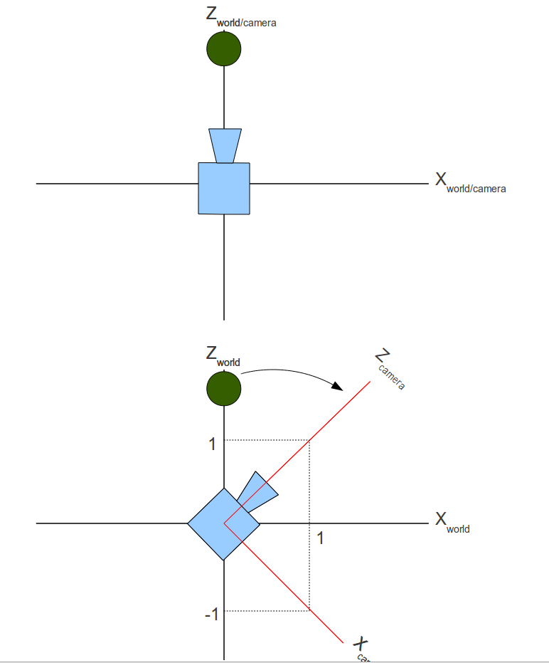
要想得到物体从世界坐标系转换到摄像机坐标系,其实就是个坐标系转换的问题。
我们首先把摄像机移动到世界坐标原点(移动摄像机位置即可):
[ 1 0 0 -x ]
[ 0 1 0 -y ]
[ 0 0 1 -z ]
[ 0 0 0 1 ]
这样一来考虑如何变化坐标系即可: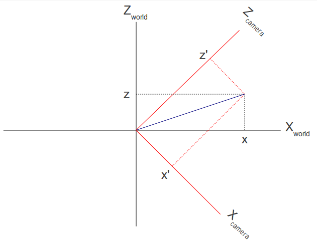
通过N,V,U,我们已经能够得出X(camera),Y(camera),Z(camera)3个基向量了。
还记得我们之前说的 – “如果把矩阵的行解释为坐标系的基向量,那么乘以该矩阵就相当于执行了一次坐标系转换。若有a*M = b,我们就可以说,M将a转换到b。”
所以:
1 | [ Ux Uy Uz 0 ] [X(world)] [X(camera)] |
结合前面提到的先把摄像机移动到世界原点,得出:
1 | [ Ux Uy Uz 0 ] [ 1 0 0 -x ] |
M(w-v)的代码实现如下:
1 | void Matrix4f::InitTranslationTransform(float x, float y, float z) |
这样一来M(w-v)也就实现了,接下来让我们看看M(v-p)是如何计算出来的吧。
M(v-p)这的p有多种投影方式,这里我只以Perspective Projection为例。
在转换到Camera坐标系后,我们还需要通过透视投影才能将3D物体映射到2D平面上。
Perspective Projection主要由下列四部分决定:
- The aspect ratio - the ratio between the width and the height of the rectangular area which will be the target of projection.
- The vertical field of view.
- The location of the near Z plane.
- The location of the far Z plane.
这一章的推导可以参考透视投影详解
一开始推导过程中不明白的一点是:
1 | 1 |
后来看了《Mathematics for 3D Game Programming and Computer Grahpics 3rd section》的5.4.1 Depth Interpolation后明白了,光栅化的时候对于深度的运算证明了是对Z的倒数进行插值来得到Z的值的。
所以上述公式是成立的。
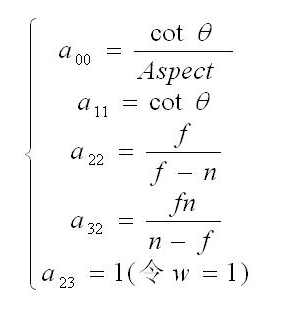
经过一系列推导后,我们得出了: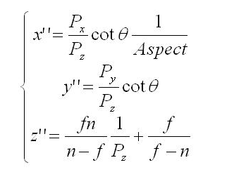
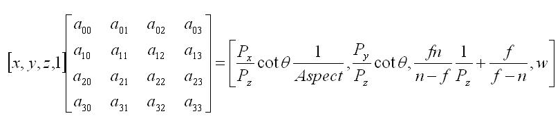
Note:
上述推导是针对DX而言的,DX和OpenGL在透视投影矩阵推导上面有一个很重要的不同,那就是DX变换后z坐标范围是[0,1],而OpenGL的z坐标范围是[-1,1]
所以如果我们把z坐标[-1,1]带入下式推导:
1 | 1 |
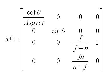
我们将得出OpenGL的透视投影矩阵如下(下面的θ = FOV/2):
1 | [cotθ/Aspect 0 0 0 ] |
所以OpenGL里M(v-p)的代码实现如下:
1 | void Matrix4f::InitPersProjTransform(const PersProjInfo& p) |
Keyboard && Mouse Control
这一章节主要是讲通过Glut提供的API如何去响应键盘和鼠标的控制。
本章节里面主要用到了两个类:
- Pipeline
- Camera
Pipeline主要是针对上一章节我们对于如何通过矩阵变化把物体显示到2D平面上的抽象:
M(m-w) – 物体坐标系到世界坐标系
M(w-v) – 世界坐标系到观察坐标系
M(v-p) – 投影变换
N = M(m-w) × M(w-v) × M(v-p)
V’ = V × M(m-w) × M(w-v) × M(v-p) = V × N
Pipeline只要知道了物体S,R,T信息就可以得出M(m-w),知道了Camera信息就可以得出M(w-v),知道了透视投影信息就可以得出M(v-p)。
我们通过修改摄像机的相关信息得出在移动摄像机后的N,并作用于物体,这样一来就能使物体显示在正确位置了。
而Camera类是对摄像机的抽象。
Pipeline和Camera的源代码可在Modern OpenGL Tutorials下载
这里我只关心针对键盘和鼠标的响应的相关代码:
Glut里针对键盘和鼠标的API主要是下列几个:
- glutSpecialFunc() – 主要是针对特殊按键比如F1
- glutKeyboardFunc() – 主要是针对普通按键比如A,B,C……
- glutPassiveMotionFunc() – 主要是针对在没有鼠标按键被按下的情况下,鼠标在窗口内移动的情况
- glutMotionFunc() – 主要是针对在鼠标按键被按下的情况下,鼠标在窗口内移动的情况
相关代码:
1 | static void SpecialKeyboardCB(int Key, int x, int y) |
final result: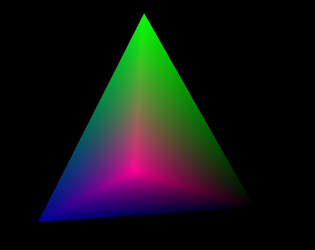
Texture Mapping
“Textures are composed of texels, which often contain color values.”
“Textures are bound to the OpenGL context via texture units, which are represented as binding points named GL_TEXTURE0 through GL_TEXTUREi where i is one less than the number of texture units supported by the implementation.”
The textures are accessed via sampler variables which were declared with dimensionality that matches the texture in shader
在真正接触Texutre之前,让我们理解下下列几个重要的概念:
Texture object – contains the data of the texture image itself, i.e. the texels(可以看出Texture object才是含有原始数据信息的对象)
Texture unit – texture object bind to a ‘texture unit’ whose index is passed to the shader. So the shader reaches the texture object by going through the texture unit.(我们访问texture数据信息并不是通过texture object,而是在shader里通过访问特定索引的texture unit去访问texture object里的数据)
Sampler Object – configure it with a sampling state and bind it to the texture unit. When you do that the sampler object will override any sampling state defined in the texture object.(Sampler Object一些sampling的配置信息,当用于texture object时会覆盖texture object里的原始sampler设定)
Sampler uniform – corresponding to handle of texture unit(用于在Shader里访问texture unit,texture unit和texture object绑定,也就间接的访问了texture的原始数据)
Relationship between texture object, texture unit, sampler object and sampler uniform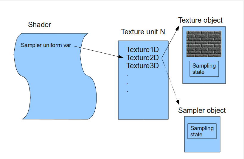
因为OpenGL没有提供从图片加载texture的API,所以这里我们需要使用第三方库来完成这项工作,这里教程上使用的是ImageMagick。
ImageMagick主要是为了从多种格式的资源文件中读取原始数据,在我们指定glTexImage2D()的原始数据的时候提供所在内存地址。
Steps to use texture mapping:
Create a texture object and load texel data into it
glGenTextures() – gen texture object
glBindTexture() – Tells OpenGL the texture object we refer to in all the following texture related calls, until a new texture object is bound.
glTexImage2D() – load texel data into texture objectInclude texture coordinates with your vertices
1 | Vertex Vertices[4] = { Vertex(Vector3f(-1.0f, -1.0f, 0.5773f), Vector2f(0.0f, 0.0f)), |
Associate a texture sampler with each texture map you intend to use in your shader
glTexParameterf() – Texture采样方式的配置
还记得我们之前讲到的Sampler object吗?这里的配置就好比我们在sampler object里配置后再作用于特定的texture object
这里我就不说关于采样方式配置相关的内容了(采样方式会决定最终像素的计算方式),这里值得一提的是mipmap的概念。
mipmap主要是由于物体在场景中因为距离的缘故会在屏幕显示的大小有变化,如果我们在物体很远,只需要显示很小一块的时候还依然采用很大的纹理贴图,最终显示在屏幕上的纹理会很不清晰(失真)。为了解决这个问题,mipmap应运而生,通过事先生成或指定多个级别的同一纹理贴图,然后在程序运作的过程中通过计算算出应该使用哪一个等级的纹理贴图来避免大纹理小色块失真的问题。
我们可以手动通过:
glTexStorage2D() && glTexSubImage2D() 去手动指定各级纹理贴图
也可以通过:
glGenerateMipmap() – 自动去生成对应的mipmap纹理贴图
而程序在实际运作过程中如何去计算Mipmap Level这里就不做介绍了,详细参考《OpenGL Programming Guide 8th Edition》的Calculating the Mipmap章节
相关函数:
textureLod()
textureGrad()Active texture unit and bind texture object to it
glActiveTexture() – 激活特定的texture unit然后绑定特定texture object到特定texture unit上
glBindTexture() – 绑定特定的texture object到texture unit上Retrieve the texel values through the texture sampler from your shader
首先我们在程序中指定了我们即将访问的Texture unit
1 | gSampler = glGetUniformLocation(ShaderProgram, "gSampler"); |
Note:
“The important thing to note here is that the actual index of the texture unit is used here, and not the OpenGL enum GL_TEXTURE0 (which has a different value).”
vsshader.vs
1 |
|
fsshader.fs
1 |
|
从上面可以看出我们在fragment shader里,通过传入的gSampler确认了使用哪一个texture unit,通过传入的TexCoord0确认了对应的纹理坐标信息去获取对应的texture信息,然后最终通过texture2D从texture里取得了特定的颜色信息作为输出,就这样纹理图片的信息就作用在了三角形上并显示出来。
final result: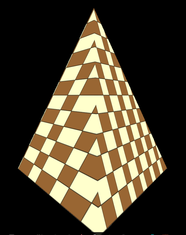
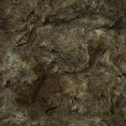
下面我简单测试了下两个Texture计算出最终纹理信息:
TextureStudy.cpp
1 | static void InitializeTextureInfo() |
fsshader.fs
1 |
|
原始图片分别为: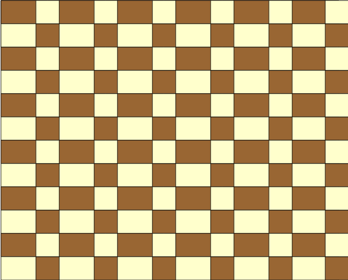
final result: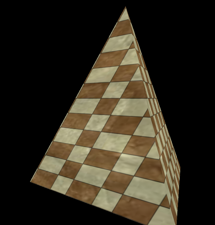
Point Sprites:
待理解学习……
Rendering to Texture Maps:
待理解学习……
Sumary:
Use immutable texture storage for textures wherever possible – When a texture is marked as immutable, the OpenGL implementation can make certain assumptions about the validity of a texture object (尽量使用不可变的texture storage, 这样OpenGL可以确保texture的有效性)
Create and initialize the mipmap chain for textures unless you have a good reason not to – improve the image quality of your program’s rendering, but also will make more efficient use of the caches in the graphics processor (为了渲染效率,减轻GPU负担,尽可能为texture创建mipmap)
Use an integer sampler in your shader when your texture data is an unnormalized integer and you intend to use the integer values it contains directly in the shader (尽量在shader里使用integer类型的sampler)
Note:
“The maximum number of texture units supported by OpenGL
can be determined by retrieving the value of the GL_MAX_COMBINED_
TEXTURE_IMAGE_UNITS constant, which is guaranteed to be at least 80 as
of OpenGL 4.0.”
Proxy texture – used to test the capabilities of the OpenGL implementation when certain limits are used in combination with each other.
Light and Shadow
光源类型:
- Ambient Light (环境光) – 环境光只影响ambient
- Directional Light (方向光) – 方向光会影响diffuse & specular
- Point Light (点光源) – 与方向光的区别是有attenuation(衰弱)而且点光源照射物体的表面的方向不一样,同样会影响diffuse & specular
传统的光照组成:
Ambient (环境光) – 与光照的方向无关
1 | FragColor = texture2D(gSampler, TexCoord0.xy) * |
因为环境光与光照方向无关,只需考虑方向光的颜色和方向光所占比重,所以基本上主要计算归结于上述运算。
final effect: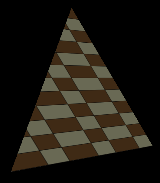
Note:
这里源代码里有个错误,在子类重写虚函数的KeyboardCB的时候,由于参数写的不对,没能正确重写该虚函数而没有被调到。
错误:
virtual void KeyboardCB(OGLDEV_KEY OgldevKey);
正确:
virtual void KeyboardCB(OGLDEV_KEY OgldevKey, OGLDEV_KEY_STATE OgldevKeyState = OGLDEV_KEY_STATE_PRESS)
Diffuse (漫反射光) – 与光照的方向和顶点normal有关
因为漫反射光要考虑光照的方向和物体的顶点法线,所以我们需要在shader里进行计算之前要把顶点的法线算出来然后传入Shader进行计算。
1 | void CalcNormals(const unsigned int* pIndices, unsigned int IndexCount, Vertex* pVertices, unsigned int VertexCount) |
vsshader.vs
1 |
|
注意“Normal0 = (gWorld * vec4(Normal, 0.0)).xyz;” – 因为我们对于顶点法线的计算是基于物体没有移动变化之前的,所以我们真正计算所用的顶点法线需要通过世界坐标系矩阵的转换。
fsshader.fs
1 |
|
从“float DiffuseFactor = dot(normalize(Normal0), -gDirectionalLight.Direction);”可以看出,光照的方向和顶点法线之间的角度直接决定了漫反射光所占的比重。
参见Lambert’s cosine law
final effect: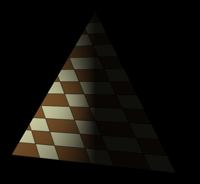
Note:
这里我按照官网和源代码的方式按自己的方式写了,但不知道为何DiffuseFactor得出的值当我去做if else判断等,无论是>0,<0,==0都不会进去,都只会进入最终的else。
我通过gDEBugger查看了uniform的值没有问题,C++那一侧所有的相关计算的值也都正确,这里弄了半天也没有解决,本来准备用Nsight调试GLSL的,发现我的笔记本好像不被支持。
个人最终认为是顶点的法线在传递给Shader的时候出问题了,导致dot之后计算DiffuseFactor出问题,虽然在VS一侧下的断点查看normal是正确的,但不确定为什么shader一侧获得的值会有问题。(这一结论主要是因为同样的shader代码在加载现有模型的时候起作用发现的)
Specular (镜面反射光) – 与光照的方向和eye观察还有顶点normal有关
Specular在Diffuse的基础上,还要多考虑一个因素(观察者所在位置,如果观察者正好在反光处,那么该观察点就会比在其他位置的观察点观察同一位置的看起来更亮)。但现实中并不是所有物体都有这一特性,所以Specular更针对物体材质而言而非光线本身。
看一下下图: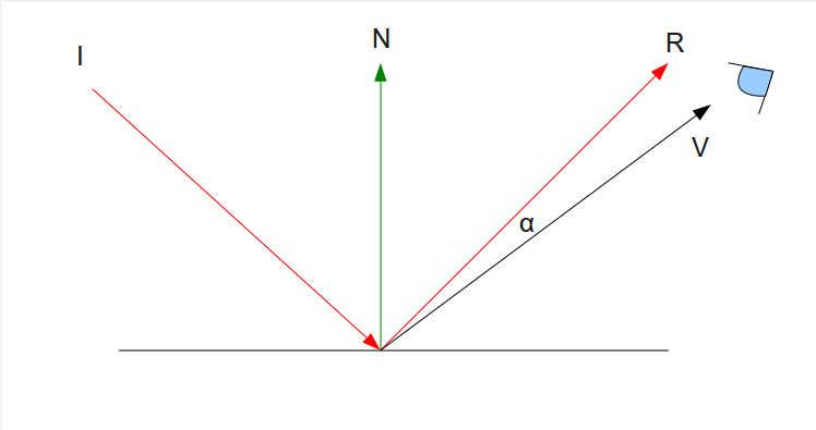
I是光线入射方向
N是平面法线
R是完美反射后的光线
V是观察者观察方向
a是观察者方向与完美反射光线的夹角
从上图可以看出当观察者所在观察角度V与R越接近时,我们可以理解为观察者观察该点会达到最大量值
我们计算出R主要是通过I和N和-N之间的计算:
详情见下图: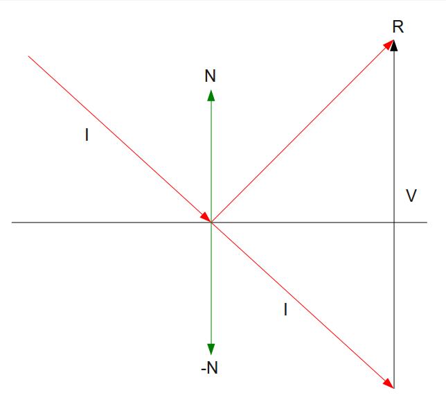
R = I + V
V = 2 * N * dot(-N,I)
这里值得一提的是OpenGL里提供了reflect方法,通过光线和平面法线就能直接算出反射R
让我们直接看一下Specular的计算公式: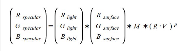
M – 是跟物体材质有关的,材质决定了specular的反光系数
p
(R.V) – 是指观察者所在位置和完美反射光线之间夹角的P次方,P是shininess factor(発光系数之类的)
上述换成代码如下:
1 | vec3 VertexToEye = normalize(gEyeWorldPos - WorldPos0); |
Limitations of the Classic Lighting Model: (传统光源的不足之处)
Big Missing:
- Assume no other objects blocking the path of the lights to the surface (假设光不会被物体遮挡)
- Accurate ambient lighting (统一固定精确的环境光,现实中是由削弱的(attenuation))
了解了光源的三个组成,也了解了传统光源的不足,让我们来看看另一种光照Point Light:
Point Light是有伴随距离而削弱(attenuation)的光源
公式如下: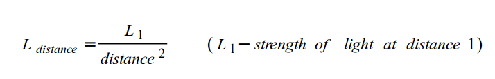
在实现Point Light的计算的时候,我们只需要把光照的方向根据Point Light位置算一下,并在最后除以根据物体位置与Point Light的光源位置算出的attenuation即可、
1 | vec4 CalcPointLight(int Index, vec3 Normal) |
接下来我们看一下Spot Light:
Spot Light和Point Light的主要区别在于,Spot Light定义了一个可影响的范围Cone和其垂直照射的方向。
而这个Cone通过Cutoff来定义:
Cutoff – “ The cutoff value represents the maximum angle between the light direction and the light to pixel vector for pixels that are under the influence of the spot light.”
见下图: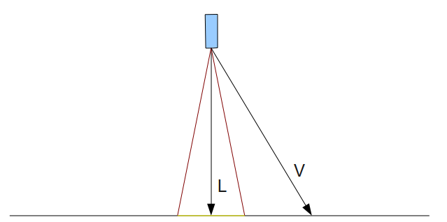
通过计算出所在点是否在Spot Light的Cone里去决定是否影响该颜色值。
这里需要关注的一点是关于如何映射Cutoff值到[0,1],因为一般来说Cutoff的值不可能设置到0(即90度),所以我们要想计算边缘化削弱效果,我们需要对Cutoff的值进行线性插值。
推导见如下(来源之OpenGL Tutorial 21):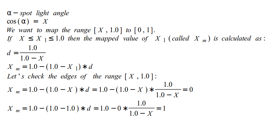
知道了怎么确认是否影响该点颜色,以及如何插值获取影响值,那么最终归结代码见如下:
1 | vec4 CalcSpotLight(struct SpotLight l, vec3 Normal) |
More Advanced Lighting Model:
Hemisphere Lighting:
The idea behind hemisphere lighting is that we model the illumination as two hemispheres. The upper hemisphere represents the sky and the lower hemisphere represents the ground
Imaged-Based Lighting:
“It is often easier and much more efficient to sample the lighting in such environments and store the results in one or more environment maps”
Lighting with Spherical Harmonics:
“This method reproduces accurate diffuse reflection, based on the content of a light probe image, without accessing the light probe image at runtime”
总结:
Ambient (环境光) – 与光照的方向无关
环境光不会削弱不考虑方向,所以只需考虑光照颜色和平面颜色即可
Diffuse (漫反射光) – 与光照的方向和顶点normal有关
光照的方向和顶点法线之间的角度直接决定了漫反射光所占的比重。
Specular (镜面反射光) – 与光照的方向和eye观察还有顶点normal有关
观察者所在位置和光照方向和法线会决定观察者所在位置的Specular反射比例,物体材质会决定Specular反射系数。
最终通过计算环境中所有光源对物体的ambient, diffuse, specular影响计算出物体的最终color
接下来我们看一个真实渲染过程中比较重要的技术 – Shadow Mapping
Shadow Mapping – Uses a depth texture to determine whether a point is lit or not.
Shadow mapping is a multipass technique that uses depth textures to provide a solution to rendering shadows (核心思想是通过比较通过光源点观察保存的深度信息(depth texture)和从观察点观察的深度信息来判断哪些点是shadowed,哪些是unshadowed – 注意比较的是通过映射到2D depth texture后的信息)
A key pass is to view the scene from the shadow-casting light source rather than from the final viewpoint
Two passes:
- First Pass
Shadow map – by rendering the scene’s depth from the point of the light into a depth texture, we can obtain a map of the shadowed and unshadowed points in the scene
在第一个pass中,我按照事例代码中写了,但发现最后显示的是纯白色的图像。
后来就不断去查问题。
首先,我怀疑depth texture是不是没有生成成功?
1 | // Create the FBO |
但上述代码没有报任何错误,通过gDebugger查看Texture的时候发现depth texture是生成成功了的。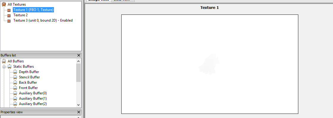
从上图仔细看,模型的深度信息时被生成到了FBO 1所绑定的Depth Texture中了的。
那么接下来,我就怀疑是不是我激活的Texture unit有错误?
以下是将Depth Texture渲染到一个平面上的代码。
1 | void ShadowMapFBO::BindForReading(GLenum TextureUnit) |
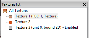
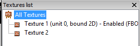
通过上图,我发现我自己的代码有三个Texture被生成,但Demo只有两个,并且我自己写的代码Enable的并非FBO 1绑定生成的Texture而是第三个Texture,所以这是我怀疑我在加载Mesh的时候加载了第三个Texture并将其绑定在了Texture unit 0,而我碰巧激活了这一个Texture unit。
由于我的mesh.cpp是沿用上一个tutorial的代码,所以我没有更新到最新教程的mesh代码。
下面是我所用的mesh.cpp的一个加载Texture的方法和Texture源代码加载的时候的方法
1 | bool Mesh::InitMaterials(const aiScene* pScene, const std::string& Filename) |
从上面可以看出如果我加载的mesh没有含有贴图的话,我会指定他去默认加载white.png作为贴图,并且渲染的时候激活Texture unit 0并将该纹理绑定到Texture unit 0
这也就是为什么我后来调用下列代码出现了Active错误的texture的原因。
1 | glUniform1i(gTextureLocation, 0); |
所以在不改Texture和Mesh源代码的情况下,我只需要将生成的Texture unit绑定到GL_TEXTURE2并指定Shader去访问Texture unit 2即可。
将上述代码改为如下即可:
1 | glUniform1i(gTextureLocation, 2); |
在渲染到Depth Texture的时候,主要是通过以下步骤:
- 创建新的FBO和Texture object
1 | // Create the FBO |
- 激活新的FBO并绑定Texture object到FBO的Depth buffer上
1 | glBindFramebuffer(GL_FRAMEBUFFER, m_fbo); |
- 关闭颜色写入到新的FBO。因为我们只需要Depth信息,所以我们不需要写入颜色信息到新的FBO里。
1 | glDrawBuffer(GL_NONE); |
- 检查新的FBO的状态是否完整
1 | GLenum Status = glCheckFramebufferStatus(GL_FRAMEBUFFER); |
- 激活新的FBO并清除Depth信息后以光线来源的角度draw call写入depth信息到新的FBO和绑定的depth texture里
1 | static void ShadowMapPass() |
- Second Pass
Rendering the scene from the point of view of the viewer. Project the surface coordinates into the light’s reference frame and compare their depths to the depth recorded into the light’s depth texture. Fragments that are further from the light than the recorded depth value were not visible to the light, and hence in shadow
第二个pass的关键有下列几个点:
- 正常方式渲染时,通过传递Light的MVP去计算每一个顶点在光源角度观察时的投影位置信息。
1 | void RenderPass() |
- 然后通过把光源角度下投影的位置信息转换到NDC space(设备坐标系,光栅化后xyz都映射到[-1,1]),这时就得到了顶点在光源角度下NDC的坐标信息。
1 | //lighting.fs |
- 最后通过转换纹理坐标映射到[0,1]去查询Depth texture中的深度信息和自身的z深度信息作比较,如果depth texture中值更小说明改点处于被遮挡区域应该是阴影部分。
1 | float CalcShadowFactor(vec4 LightSpacePos) |
因为原本x,y,z在NDC space下是[-1,1],为了映射到[0,1],我们只需要按上述方法即可。
这样一来就得到NDC space下的纹理坐标信息和深度z信息,然后通过查询depth texture获取光源角度的深度信息和现有顶点在光源角度的深度信息做比较得出是否处于阴影的结论。
这里实现相当复杂就没有自己再去写一遍,具体参考Tutorial 24的源代码。
最终效果: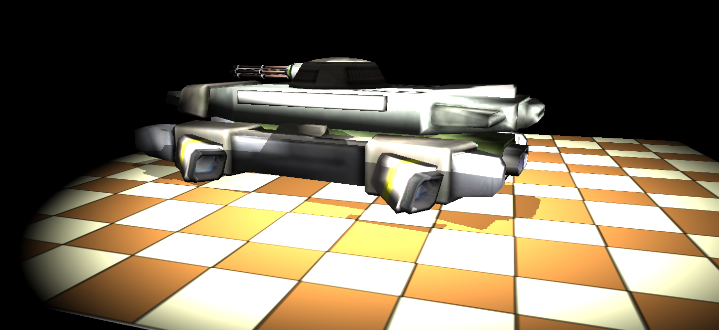
Skybox
A skybox is a method of creating backgrounds to make a computer and video games level look bigger than it really is. When a skybox is used, the level is enclosed in a cuboid. (From wiki)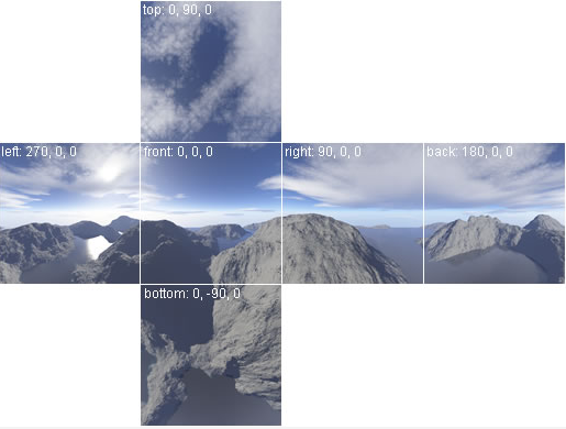
在OpenGL中实现Skybox是通过Cubemap。
In order to sample from the cubemap we will use a 3D texture coordinate instead of the 2D coordinate
Skydome – A skybox which uses a sphere is sometimes called a skydome.
实现skybox主要有下列几点需要注意:
- 生成Cubemap texture,分别指定6个对应skybox的六个面类型的纹理数据
1 | static const GLenum types[6] = { GL_TEXTURE_CUBE_MAP_POSITIVE_X, |
- 渲染skybox的时候,需要把glCullFace和glDepthFunc设置成GL_FRONT和GL_LEQUAL(因为camera是放在skybox sphere内部的,而sphere的triangle是front face, 所以针对skybox sphere我们需要cull的是front而非back。为了使得skybox永远不会被clip掉,我们需要修改默认的glDepthFunc到GL_LEQUAL来确保在Z = 1的far平面也不会被clip。)
1 | void SkyBox::Render() |
- 确保skybox深度检测时值永远在Z = 1的far平面(这样一来确保skybox深度检测永远失败,因为我们吧glDepthFunc设置成了GL_LEQUAL)
1 | skybox.vs |
- 把object space的3D坐标当做3D texture坐标的索引值去查询纹理信息
1 | skybox.vs |

Note:
“An interesting performance tip is to always render the skybox last (after all the other models). The reason is that we know that it will always be behind the other objects in the scene.”
Normal Mapping
在了解Normal Mapping之前不得不提Bump Mapping
下列关于Bump Mapping大部分内容来源:
OpenGL 法线贴图 切线空间 整理
Bump mapping
关于法线贴图, 法线, 副法线, 切线 的东东,看了很容易理解
可以看出Bump Mapping是通过改变物体顶点法线来影响光照的效果,最终看起来有凹凸的效果(而非顶点之间真实的深度差),是一种欺骗眼睛的技术。
“Jim Blinn在1978发表了一篇名为:“Simulation of Wrinkled Surfaces”,提出了Bump Mapping这个东东。Bump Mapping通过一张Height Map记录各象素点的高度信息,有了高度信息,就可以计算HeightMap中当前象素与周围象素的高度差,这个高度差就代表了各象素的坡度,用这个坡度信息去绕动法向量,得到最终法向量,用于光照计算。坡度越陡,绕动就越大。”
Why Bump Mapping?
“如果要在几何体表面表现出凹凸不平的细节,那么在建模的时候就会需要很多的三角面,如果用这样的模型去实时渲染,出来的效果是非常好,只是性能上很有可能无法忍受。Bump Mapping不需要增加额外的几何信息,就可以达到增强被渲染物体的表面细节的效果,可以大大地提高渲染速度,因此得到了广泛的应用。”
What is Normal Mapping?
“Normal Mapping也叫做Dot3 Bump Mapping,它也是Bump Mapping的一种,区别在于Normal Mapping技术直接把Normal存到一张NormalMap里面,从NormalMap里面采回来的值就是Normal,不需要像HeightMap那样再经过额外的计算。”
“值得注意的是,NormalMap存的Normal是基于切线空间的,因此要进行光照计算时,需要把Normal,Light Direction,View direction统一到同一坐标空间中。”
这里不得不提的一个点就是切线空间(tangent space)
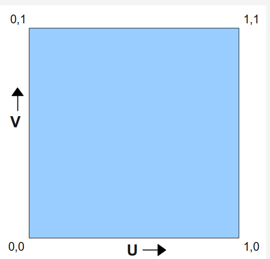
What is tangent space?
“ Tangent Space与World Space,View Space其实是同样的概念,均代表三维坐标系。在这个坐标系中,X轴对应纹理坐标的U方向,沿着该轴纹理坐标U线性增大。Y轴对应纹理坐标的V方向,沿着该轴纹理坐标V线性增大。Z轴则是UXV,垂直于纹理平面。”
Why do we need tangent space?
“为什么normal map里面存的法线信息是基于tangent sapce而不是基于local space呢?基于local space理论上也是可以的,但是这样的normal map只能用于一个模型,不同把这个normal map用于其他模型。比如说建模了一个人,并且生成了该模型基于local space的normal map, 如果我们建模同一个人,但是放的位置和角度和之前的不一样,那么之前的normal map就不能用了,因为local Space并不一样,但如果我们normal map里存的是tangent space的normal的话,就不存在这个问题,因为只要模型一样,模型上每个点的tangent space就是一样的,所谓以不变应万变。”
可以看出tangent space是针对顶点而言的。
How to get tangent space?
让我们看一下下图: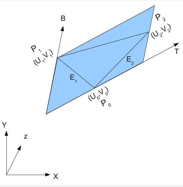
以下推导来源于:
Tutorial 26:Normal Mapping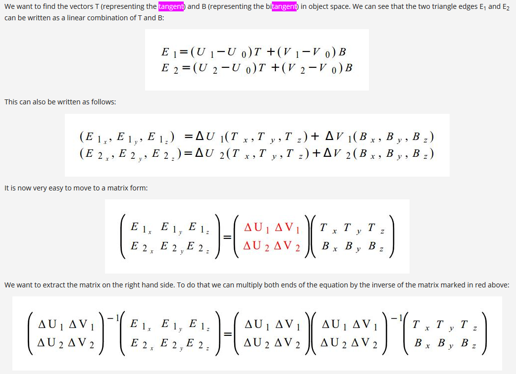
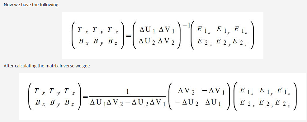
从上面而已看出通过三角形的顶点和纹理信息可以算出T和B
Note:
在实际开发中我们并非一定要手动写代码运算,比如”Open Asset Import Library就支持flag called ‘aiProcess_CalcTangentSpace’ which does exactly that and calculates the tangent vectors for us”
Normal Map也通过工具可以生成,比如3D Max, Maya, 教程里用的GNU Image Manipulation Program (GIMP)…….
当我们通过Normap Map获取得到normal值时,因为该normal值时位于tangent space下,所以我们必须对其进行坐标系转换,必须转换到world space后才参与光照计算。
而这个变换到世界坐标系的矩阵,可以通过tangent这个向量和顶点法线信息推导出来。
- 加载mesh时生成tangent数据,渲染时指定tangent数据位置
1 | bool Mesh::LoadMesh(const std::string& Filename) |
1 | void Mesh::Render() |
- 将tangent和顶点法线转换到世界坐标系
1 | layout (location = 0) in vec3 Position; |
通过转换到世界坐标系的tangent和normal计算出bitangent(转换到世界坐标系后的B)(下面T代表tangent, N代表normal, B代表bitangent)
逆算出tangent space下normal map里的顶点法线值
通过算出的位于世界坐标系的TBN去转换tangent space下逆算后的normal map的顶点法线值,最终得到位于世界坐标的顶点法线
算出位于世界坐标系的顶点法线后,最后正常参与diffuse光照计算即可
1 | (lighting.fs:132) |
让我们看看Normal Map Texture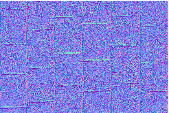
See Normal Mapping(left) and Regular Mapping(right)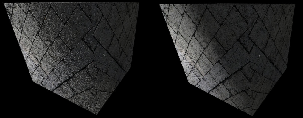
高模normal map用于低模模型上,即不增加渲染负担又能增加渲染细节。
More:
下面内容来源
Parallax Mapping
当使用Normal Mapping技术时,并没有把视线方向考滤进去。在真实世界中,如果物体表面高低不平,当视线方向不同时,看到的效果也不相同。Parallax Mapping就是为了解决此问题而提出的。
Parallax Mapping首先在一篇名为“Detailed Shape Representation with Parallax Mapping”的文章中提出。它的基本思想如下图示(本图来自Parallax Mapping with Offset Limiting: A PerPixel Approximation of Uneven Surfaces)。在图示的视线方向,如果表面是真正的凹凸不平的,如real surfacer所示,那么能看到的是B点,因此用于采样法线的正确纹理坐是TB而不是TA。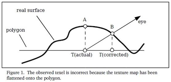
因此,我们需要对纹理坐标作偏移,为了满足实时渲染的要求,采用了取近似偏移的方法(如下图示),这种近似的算法已经可以达到比较好的效果。具体的offset计算可以参考:“Parallax Mapping with Offset Limiting: A PerPixel Approximation of Uneven Surface”,里面有详细的讲解。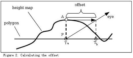
Parallax Occlusion Mapping
Parallax Occlusion Mapping是对Parallax Mapping的改进,DirectX SDK中有个Sample专门讲这个,相关细节可以参看此Sample. Parallax Occlusion Mapping中实现了Self Shadow,还计算了比较精确的offset,复杂度比Parallax Mapping大,但是实现效果更好。
BillBoard And Geometry Shader
Geometry shader(Optional)
“The geometry shader sits logically right before primitive assembly and fragment shading.”
Receives as its input complete primitives as a collection of vertices, and these inputs are represented as array (Geometry shader接收完整图形的顶点集合,这些顶点集合在geometry shader中通过gl_in[]数组的方式访问)
gl_in的声明:
1 | in gl_PerVertex { |
Geometry Features:
Producing Primitives
They can have a different primitive type for their output than they do for their input. (EG: wireframe rendering, billboards and even interesting instancing effects)(Billboard效果见后面)Culling Geometry
Selective culling (geometry shader通过对特定的gl_PrimitiveIDIn进行生成特定的primitive实现selective culling)
“gl_PrimitiveIDIn is a geometry language input variable that holds the number of primitives processed by the shader since the current set of rendering primitives was started.”Geometry Amplification
Produces more primitives on its output than it accepts on its input
(can be used to implement fur shells or moderate tessellation – 因为可以对传入的primitive数据进行处理并生成多个primitive,所以能通过复制并改变primitive的信息数据来实现毛发等效果)
Gl_MaxGeometryOutputVertices & glGetIntegerv(GL_MAX_GEOMETRY_OUTPUT_VERTICES)
毛发效果(来源OpenGL红宝书第八版):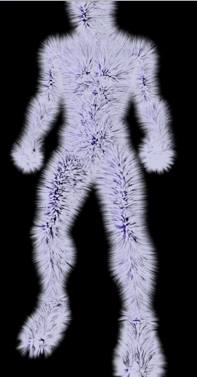
Geometry Shader Instance
Only runs the geometry shader and subsequent stages (rasterization) multiple times, rather than the whole pipeline (Geometry shader instancing draw call是通过运行多次geometry和rasterization和fragment来实现的)
Geometry shader instancing is enabled in the shader by specifying the invocations layout qualifier
1 | //gl_InvocationID identifies the invocation number assigned to the geometry shader invocation. |
Multiple Viewport Rendering
gl_ViewportIndex (output variables available in the geometry shader that can redirect rendering into different regions of the framebuffer)
gl_ViewportIndex is used to specify which set of viewport parameters will be used to perform the viewport transformation by OpenGL
“ (Multiple viewport concept (多个视图窗口) – 这里主要是通过gl_ViewportIndex访问多个viewport,然后在geometry shader中通过指定primitive输出到特定的viewport来实现多个视图窗口)
glViewportIndexedf() or glViewportIndexedfv() – specify how window x and y coordinates are generated from clip coordinates
glDepthRangeIndexed() – specify how the window z coordinate is generated
效果展示(这里展示的OpenGL红宝书第八版的例子):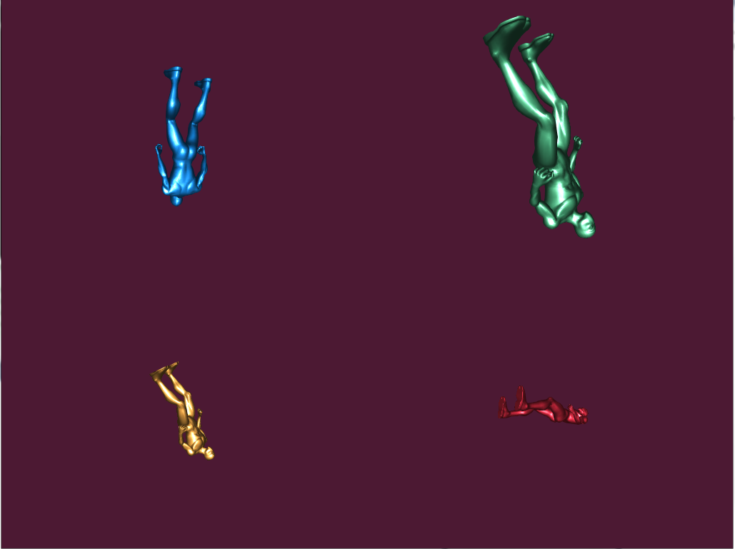
Layer Rendering
It is also possible to use a 2D array texture as a color attachment and render into the slices of the array using a geometry shader (传入2D的纹理数组数据当做color attachment,通过geometry shader把传入的2D纹理数组信息去渲染多个slices)
A restriction exits when using layered attachments to framebuffer: (使用layered attachment到framebuffer的规则):
All the attachments of that framebuffer must be layered (framebuffer的所有attachment都必须是layered)
Also, all attachments of a layered framebuffer must be of the same type (所有attach到layered framebuffer的attachment必须是同样类型)
gl_Layer – built in variable in geometry shader – that is used to specify the zero-based index of the layer into which rendering will be directed
可实现的效果好比:
Cube-Map
添加cube_map texture为color attachment到framebuffer中
cube-map texture(2D texture)这里会被划分成六个layer的array texture
通过instanced geometry shader生成六个faces(对应六个layer),通过gl_InvocationID和gl_Layer访问六个faces并做相应的projection matrices运算实现Cube_Map Face的效果Advanced Transform Feedback
这里首先要了解下什么是Transform Feeback?
Transform feedback can be considered a stage of the OpenGL pipeline that sits after all of the vertex-processing stages and directly before primitive assembly and rasterization. Transform feedback captures vertices as they are assembled into primitives and allow some or all of their attributes to be recorded into buffer objects. (Transform feedback发生在所有顶点运算阶段之后(所以如果geometry shader打开了,transform feedback就发生在geometry shader之后,相反是在vertex shader之后),在primitive assembly和光栅化之前。Transform feedback可以保存顶点的一些属性信息用于下一次的运算。)
Why do we need transform feedback?
“DirectX10 introduced a new feature known as Stream Output that is very useful for implementing particle systems. OpenGL followed in version 3.0 with the same feature and named it Transform Feedback. The idea behind this feature is that we can connect a special type of buffer (called Transform Feedback Buffer right after the GS (or the VS if the GS is absent) and send our transformed primitives to it. In addition, we can decide whether the primitives will also continue on their regular route to the rasterizer. The same buffer can be connected as a vertex buffer in the next draw and provide the vertices that were output in the previous draw as input into the next draw. This loop enables the two steps above to take place entirely on the GPU with no application involvement (other than connecting the proper buffers for each draw and setting up some state).”
从上面可以看出,transform feedback可以帮助我们在构建primitive之前保存顶点相关的一些信息参与到下一次draw的运算且不用参与到Clipping,rasterizer和FS。最重要的是所有这一切都发生在GPU上,不需要从GPU上copy数据到CPU上做运算。
大致情况如下图: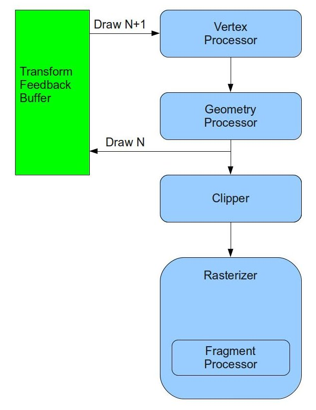
了解一些相关概念:
Transform Feedback Objects:
“The state required to represent transform feedback is encapsulated into a
transform feedback object.”(transform feedback objects主要是存储跟transform feedback相关的一些状态。比如:哪一个buffer绑定到了transform feedback buffer的binding point)
Transform Feedback Buffer:
vertex shader或geometry shader中获取来的信息,这里的TFB是指通过glBindBufferBase之类方法后被绑定到Tansform Feedback Objects上的buffer
glBindBufferBase调用的时候需要指定index作为binding point,如果我们想要把Transform Feedback Buffer的数据存储在多个buffer的时候我们可以把多个buffer绑定到不同的binding point上,然后通过glTransformFeedbackVaryings传入的参数格式决定我们生成的数据是如何写入到各个buffer里的。
具体的glTransformFeedbackVaryings如何配置决定数据是如何写入到各个buffer的参见OpenGL红宝书Configuring Transform Feedback Varyings
因为粒子效果用到了Billboard来展示,所以在了解Particle System之前,我们先来看看Billboard是如何通过GS实现的:
Billboard - “A billboard is a quad which always faces the camera. “
- Before a geometry shader may be linked, the input primitive type, output primitive type, and the maximum number of vertices that is might produce must be specified (在链接geometry shader之前,我们必须先定义geometry shader的输入输出类型)
1 | version 330 |
- 利用传递进来的顶点primitive数据生成新的面向camera的primitive数据
1 |
|
EmitVertex() - produces a new vertex at the output of the geometry shader. Each time it is called, a vertex is appended to the end of the current strip (将新的vertex加入到primitive的队列)
EndPrimitive() - breaks the current strip and signals OpenGL that a new strip should be started the next time EmitVertex() is called (将之前所加入的vertex算作一个primitive的信息,通知OpenGL开始下一个primitive的构造)
Note:
When the geometry shader exits, the current primitive is ended implicitly (如果geometry shader结束了,那么当前还没有调用EndPrimitive()的primitive将视作结束)
When EndPrimitive() is called, any incomplete primitives will simply be discarded (当EndPrimitive()被调用的时候,数据不完全的primitive将被抛弃 -- 不调用这个方法的primitive相当于culling掉)
- 在FS中利用GS中生成的纹理坐标映射纹理信息并Cull掉纹理图片中黑色的部分
1 |
|
Final Effect: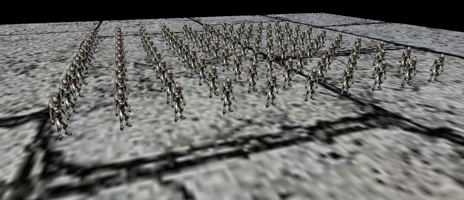
接下来我们看看通过Transform Feedback实现Particle System的步骤:
- 生成Transform Feedback Objets和用于存储数据的buffer,并将buffer绑定到特定Transform Feedback Objects上
1 | bool ParticleSystem::InitParticleSystem(const Vector3f& pos) |
- 配置Transform Feedback Varyings(指定我们会如何在GS中去如何记录和存储哪些信息)
1 | bool PSUpdateTechnique::Init() |
- 配置设定一些Update Shader和Billboard Shader的一些数据信息
1 | bool ParticleSystem::InitParticleSystem(const Vector3f& pos) |
- 一次Draw Call,两个Pass,一个Pass去更新TFB里的数据,一个Pass去渲染TFB里的数据
1 | static void RenderPass() |
- 接下来就是看Update Shader是如何去更新模拟粒子的生成和重力效果的,billboard Shader是如何将生成的顶点粒子数据渲染到屏幕上的
1 | ps_update.vs |
通过glDEBugger我们可以查看到Transform Feedback生成的数据信息: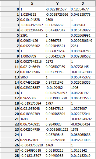
Final Effect: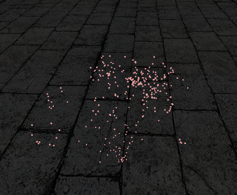
接下来让我们来看看Transform Feedback的更多高级使用:
Multiple Output Steams
Multiple streams of vertices can be declared as outputs in the geometry shader (通过stream我们可以把一些额外需要保存的信息保存到特定的stream里便于transform feedback buffer去访问并进行进一步的处理)
Using the stream layout qualifier – this layout qualifier may be applied globally, to an interface block, or to a single output declaration
Each stream is numbered, starting from zero, max number of streams – GL_MAX_VERTEX_STREAMS
When the stream number is given at global scope, all subsequently declared geometry shader outputs become members of that stream until another output stream layout qualifier is specified
See how to declaration stream: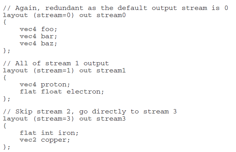
Multiple output stream’s built in GLSL functions:
EmitStreamVertex(int stream)
EndStreamVertex(int stream)
glTransformFeedbackVaryings() – tell OpenGL how those streams are mapped into transform feedback buffer (告诉OpenGL各个stream是怎么映射到transform feedback buffer的)
When multiple streams are active, it is required that variables associated with a single stream are not written into the same buffer binding point as those associated with any other stream(当多个stream声明激活的时候,我们必须将每一个stream写到不同的buffer binding point里)
gl_NextBuffer is used to signal that the following output variables are to be recorded into the buffer object bound to the next transform feedback binding point (gl_NexBuffer告诉OpenGL后面的数据将绑定到下一个transform feedback buffer)
if rasterization & fragment shader are enabled, the output variables belonging to stream 0 will be used to form primitives for rasterization and will be passed into the fragment shader. Output variables belonging to other streams will not be visible in the fragment shader and if transform feedback is not active, they will be discarded (这里需要注意,一旦rasterization 和 fragment shader被开启或者transform feedback没有被开启,那么geometry shader里面指定的out变量只有属于stream 0的才会被进行处理,其他都会被抛弃)
Note:
When multiple output streams are used in a geometry shader, they must all have points as the primitive type (注意,当multiple output streams被开启时,geometry shader必须指定输出类型为point,当first pass的时候geometry shader指定输出类型为point,second pass的时候geometry shader可以针对第一次transform feedback记录的point数据进行处理输出triangle等)
Primitive Queries
Reason:
Geometry shader can emit a variable number of vertices per invocation (因为geometry shader会扩展出很多primitive和vertices,我们在访问一些跟transform feedback buffer相关的数据的时候就不那么直接 – 这里要提一下没有geometry shader,vertex shader结合transform feeback buffer的使用是一对一的输出,而geometry shader不一样,会有一堆多的primitive,vertices的输出)
Problem:
The number of vertices recorded into transform feedback buffers when a geometry shader is present may not be easy to infer
Solution:
Two types of queries are available to count both the number of primitives the geometry shader generates, and the number of primitives actually written into the transform feedback buffers(通过Primitive Queries我们可以得知geometry shader的primitives,vertices生成数量和实际被写入transform feedback buffer的primitive,vertices数量)
GL_PRIMITIVES_GENERATED – query counts the number of vertices output by the geometry shader – valid at any time
&
GL_TRANSFORM_FEEDBACK_PRIMITIVES_WRITTEN – query counts the number of vertices actually written into a transform feedback buffer – only valid when transform feedback is active
Due to geometry shader supports multiple transform feedback streams, primitive queries are indexed (因为geometry shader支持multiple transform feedback streams,所以primitive queries也是indexed的)
3D Picking
“The ability to match a mouse click on a window showing a 3D scene to the primitive (let’s assume a triangle) who was fortunate enough to be projected to the exact same pixel where the mouse hit is called 3D Picking.”
3D Picking实现的关键在于通过类似Shadow map的方式,把所有的primitive信息写入到一张picking texture里,当mouse点击的时候我们去查询所点击的primitive信息然后把该primitive渲染成我们想要的颜色即可。
实现步骤:
First pass(picking pass) – 利用gDrawIndex, gObjectIndex, Primitive Index生成picking texture
1 | bool PickingTexture::Init(unsigned int WindowWidth, unsigned int WindowHeight) |
通过类似生成Shaow map的方式,我们生成一个FRAMEBUFFER m_fbo,然后通过分别attach m_depthTexture和m_pickingTexture到GL_COLOR_ATTACHMENT0和GL_DEPTH_COMPONENT上,紧接着我们通过指定绘制到m_fbo的GL_COLOR_ATTACHMENT0(即我们attach的那个)上,这样一来当我们渲染到m_fbo的时候,attach到GL_COLOR_ATTACHMENT0的那个color texture就会得到渲染的picking texture,最后在我们我们在渲染之前需要指定m_fbo作为渲染到的FRAMEBUFFER。这样一来我们通过Picking Technique就能得到Picking texture。
这里也会生成depth texture,但我们并不会用到,指定生成depth texture的原因如下:
“By combining a depth buffer in the process we guarantee that when several primitives are overlapping the same pixel we get the index of the top-most primitive (closest to the camera). “(注意我们需要结合depth buffer来保证我们生成的picking texture保存的primitive信息是离摄像机最近的)
1 | picking_technique.cpp |
理解上述代码,我们首先需要看看我们存储在picking texture里的信息组成。
从picking.fs中可以看出我们存储在piking texture里的颜色信息主要是由gObjectIndex,gDrawIndex,gl_PrimitiveID组成。
当我们去渲染spider mesh的时候,我们通过调用void Mesh::Render(IRenderCallbacks* pRenderCallbacks)传入了实现了DrawStartCB回调方法的类传入了shader里gObjectIndex的值。
1 | void Mesh::Render(IRenderCallbacks* pRenderCallbacks) |
这里传入的是spider mesh count的索引,即gObjectIndex代表mesh count的索引(这里的spider由19个mesh组成,通过open3mod可以查看到)。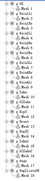
接下来当我们渲染两个spider的时候,我们把Object index(即这里spider的数量)作为了gDrawIndex传入了shader。
1 | static void PickingPhase() |
最后gl_PrimitiveID是OpenGL build-in的变量,”This is a running index of the primitives which is automatically maintained by the system.”(代表我们绘制的primitive索引值,每一次draw都会从0开始。)
这里就引出了一个问题。我们如何得知我们渲染到picking texture里的primitive值0是指background还是被object遮挡的primitive了。
这也就是为什么我们在写入picking texture的时候,gl_PrimitiveID + 1的原因了。这样一来凡是primitive为0的都是background。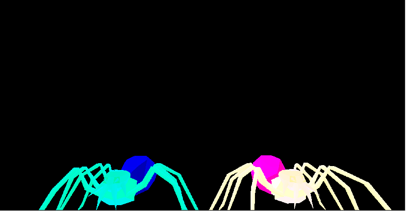
Render pass – 通过映射mouse click的pixel到picking texture,会得到鼠标点击到的gObjectIndex,gDrawIndex,gl_PrimitiveID信息,然后通过这些信息,我们把该点击的primitive通过simple color shader渲染成红色,然后再正常渲染两个spider即可。
1 | void Mesh::Render(unsigned int DrawIndex, unsigned int PrimID) |
这里去读取picking texture里的信息的时候,要注意的一点是,鼠标获取得到的坐标信息和我们去查询texture的坐标系是不一致的,这里需要转换。
一下来源于Glut Mouse Coordinates
“In “window” coordinate, the origin (0,0) is top left of the viewport.In OpenGL the origin is bottom left of the viewport. When you click glut give you the window coordinate. All you have to do is calculate this: y = height_of_viewport - y - 1.
Edit: Notice that you compare a screen coordinate (mouse click) with an object coordinate (your rectangle). This is fine if you use a perspective projection like this glOrtho(0,0,viewport_width,viewport_height). If not you need to call gluProject to map each corner of your rectangle in screen coordinate. “
从上面可以看出,glut获取的mouse坐标系是以左上角为(0,0)点。而OpenGL viewport的(0,0)点时左下角,所以我们需要通过下列方式去转换映射点:
1 | PickingTexture::PixelInfo Pixel = m_pickingTexture.ReadPixel(m_leftMouseButton.x, WINDOW_HEIGHT - m_leftMouseButton.y - 1); |
在得到正确的映射值后,我们将查询到的gObjectIndex,gDrawIndex,gl_PrimitiveID当做信息传入void Mesh::Render(unsigned int DrawIndex, unsigned int PrimID)去指定渲染特定mesh的特定primitive成红色。这里要注意的一点是因为mesh里的primitive索引是从0开始的,但我们之前存储的primitive index是+1的,所以这里我们需要恢复原有正确的值去指定渲染正确的primitive。
1 | // Must compensate for the decrement in the FS! |
这里有一个疑问没有想通,写在这里,如果有人知道答案,希望不腻赐教。第一次把特定primitive渲染成红色后再通过正常渲染渲染两个spider,那么按理,那个特定的primitve会被再次绘制渲染(正常渲染的时候),那么深度信息应该是和前一次一致的,为什么最终却显示的红色而不是模型纹理的颜色了?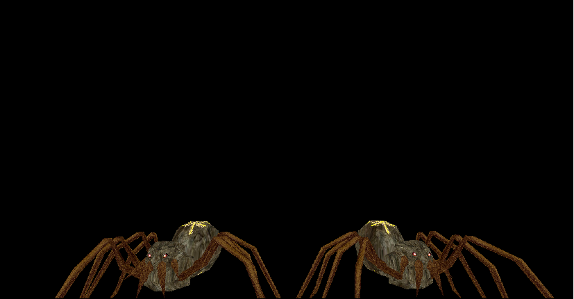
Basic Tessellation
The tessellation process doesn’t operate on OpenGL’s classic geometric primitives: points, lines, and triangles, but uses a new primitive called a patch (Tessellation shader就是针对patch来进行处理的而并非点,线,三角形)
Patch is just an ordered list of vertices (在tessellation shader里面比较重要的概念就是这个patch,patch是一系列的顶点,OpenGL规定patch的vertex数量必须至少大于等于3)。这里的Patch我们可以理解为一个包含了几何图形的所有Control Points(CP)的集合。Control Points会决定这个几何图形最终的形态。
让我们来看看Tessellation Shader在OpenGL Pipeline里的执行顺序(下图来源)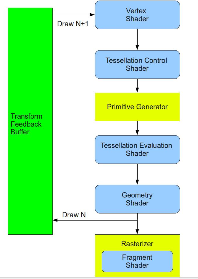
Two Shader Stage, One fixed function:
Tessellation Control Shader(TCS)
“The control shader calculates a set of numbers called Tessellation Levels (TL). The TLs determine the Tessellation level of detail - how many triangles to generate for the patch.”
可以看出TCS并不是负责顶点的细分而是负责指定细分的规则(如何细分,细分程度)。上述Tessellation Levels(TL)的计算就比较灵活,可以根据摄像机距离也可以根据屏幕最终所在像素多少来决定细分方式。
Note:
“It is executed once per CP in the output patch”Primitive Generator (Fixed function)
“OpenGL passes the output of the tessellation control shader to the primitive generator, which generates the mesh of geometric primitives and tessellation coordinates that the tessellation evaluation shader stage uses.”(PG之后会输出domain细分后的顶点和顶点纹理坐标信息,通过顶点纹理信息TES会算出对应的顶点位置信息)通过TCS指定的规则去细分。
这里需要理解一个概念 - Domain
细分的规则跟Domain的类型有关
下面我们来看看Quad Domain和Triangle Domain:
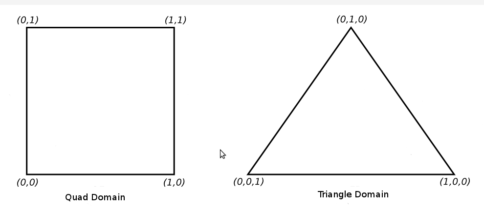
不同类型的domain – 会决定我们inner和outer的具体含义:
Quad Tessellation:
……Isoline Tessellation:
Use only two of the outer-tessellation levels to determine the amount of subdivisionTriangle Tessellation:
Triangular domains use barycentric coordinates to specify their Tessellation coordinates从上面可以看出三中不同的Domain有不同的细分规则。
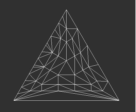
三角形是通过质心去做细分的。
下面来看看三角形细分后的结果:
Tessellation Evaluation Shader(TES)
The TES is executed on all generated domain locations.Positions each of the vertices in the final mesh (TES是针对从tessellation control shader和Primitive Generator通过细分后所有patch相关的顶点来进行运算,通过各顶点的gl_TessCoord(顶点在patch里的相对坐标信息)按不同Domain的纹理坐标计算方式计算出相应的纹理坐标,位置信息和法线信息,从而实现细分多边形和修改顶点信息效果)接下来让我们结合事例学习理解:
Basic Tessellation Tutorial
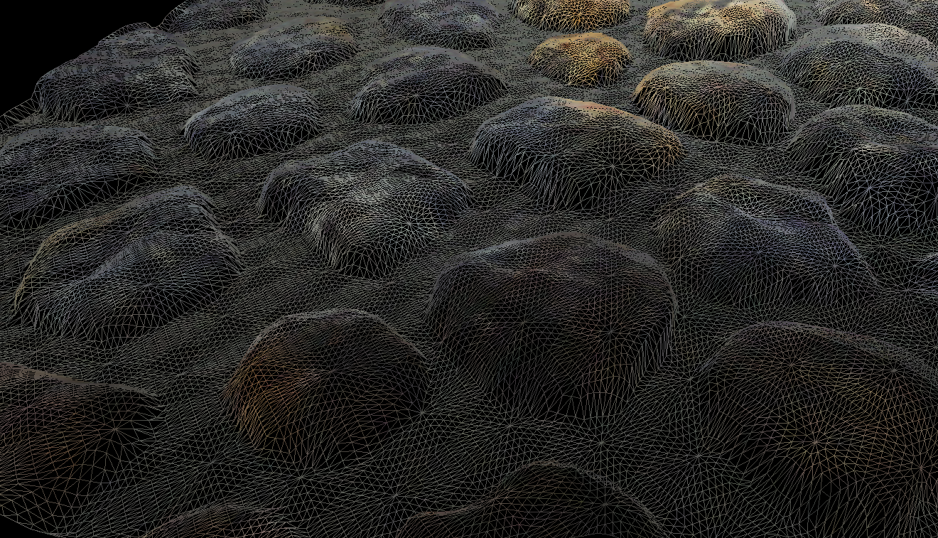
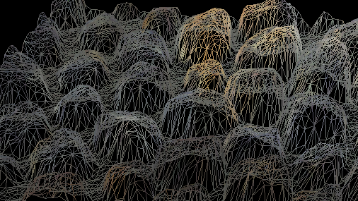
该Tutorial实现下列几个功能:根据quad.obj模型三角形边与camera的距离去决定LOD的细分程度
通过读取高度图去作为对应顶点的高度信息,且实现通过+-控制高度图的所占比例
可以通过z键开启wireframe模式查看细分情况
接下来看看主要的实现步骤:
- 加载并设置height map和color map作为高度图和纹理图
1 | static bool InitializeTesselationInfo() |
2. 编译连接含TCS和TES的Shader
1 | bool LightingTechnique::Init() |
3. 以GL_PATCHES方式绘制quad,触发Tessellation Shader
1 | void Mesh::Render(IRenderCallbacks* pRenderCallbacks) |
4. 延迟VP坐标转换(因为Tessellation Shader会细分出更多的顶点,所以这一步从VS延迟到了TES)
1 | lighting.vs |
5. TCS,指定patch顶点数量和细分方式(这里实现了细分程度跟patch各顶点到camera的距离有关)
1 | lighting.cs |
6. TES,利用细分出的所有相关patch顶点的gl_TessCoord(顶点在patch里的相对位置信息),算出各顶点的纹理坐标信息,位置信息,法线信息(这里通过读取高度图的值参与顶点的高度计算实现动态控制高度值运算),然后转换所有patch相关的顶点位置信息到投影坐标系
1 | lighting.es |
7. 存储所有细分的顶点位置信息(世界坐标系),顶点法线信息(世界坐标系)和顶点纹理坐标信息参与正常的光照计算得出最后的纹理颜色
1 |
|
8. 相关控制(高度图对顶点位置生成的控制,wireframe控制)
1 | static void KeyboardCB(unsigned char key, int x, int y) |
Final Effect: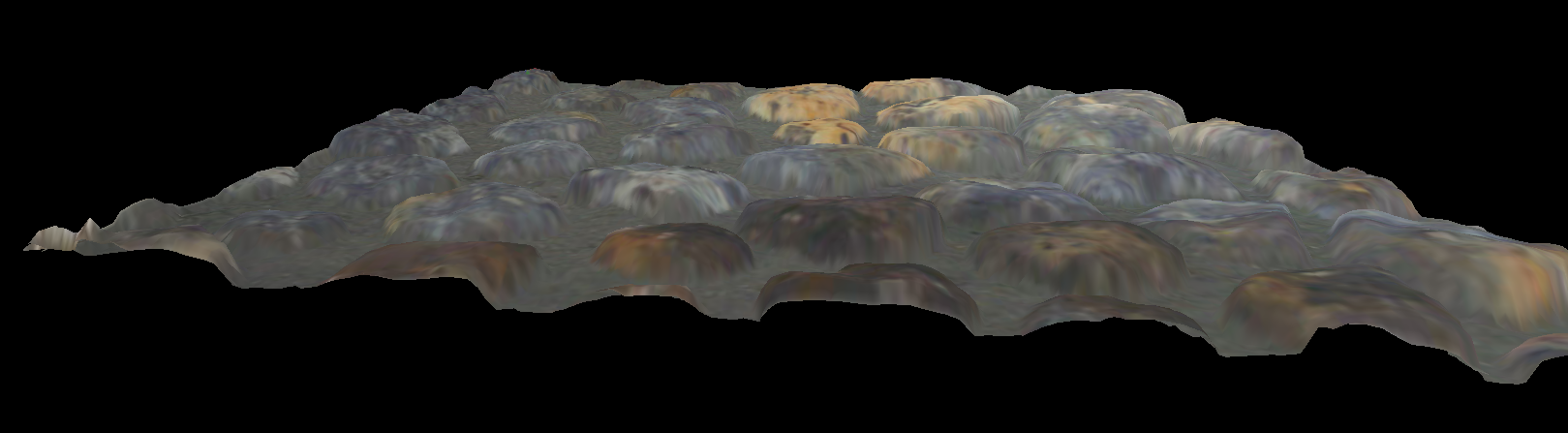

总结:
tessellation shader是可选的shader,不是必须的
tessellation shader与vertex shader不一样,tessellation shader是针对patch(一系列顶点)来处理而不是一个顶点 (因为tessellation shader需要通过传入的patch(一系列顶点)来生成新顶点的位置信息)
tessellation control shader负责对patch的细分设定(通过指定细分的计算方式可以实现LOD(level of detail – 根据与camera的距离不同而细分程度不同)等效果)
primitive generator负责对domian的细分
tessellation evaluation shader负责通过PG细分出来的顶点在patch里的坐标信息去计算顶点位置,纹理,法线信息
Bezier曲线在这里是一种细分后位置的计算方法来实现曲面的平滑效果
还有一个应用叫displacement mapping,在tessellation evaluation shader里面通过tessellation coordinate的值来映射纹理(sample a texture)
关于Bezier曲线学习,参考PN Triangles Tessellation
Vertex Array Objects
“The Vertex Array Object (a.k.a VAO) is a special type of object that encapsulates all the data that is associated with the vertex processor. Instead of containing the actual data, it holds references to the vertex buffers, the index buffer and the layout specification of the vertex itself.”
“VAOs store all of the links between the attributes and your VBOs with raw vertex data.”
从上面的定义来看,可以看出,Vertex Array Object(VAO) 主要是用于存储关联的顶点buffer索引,顶点buffer定义的数据访问格式等信息而非真正的顶点数据。当我们需要去绘制某个特定的顶点buffer的时候,我们只需要指定好该顶点buffer的数据访问格式和数据内容,然后绑定到特定的VAO,最后激活该VAO并进行会绘制即可。
让我们来看看两种存储数据的格式AOS(Array Of Structure),SOA(Structure Of Arrays):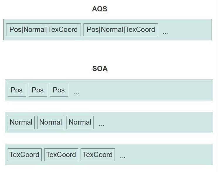
事例是采取了SOA的形式存储数据。
- 在定义VBO之前,我们需要生成VAO,并绑定到该VAO上(这样一来后续的VBO操作都会绑定到该VAO上被记录下来(比如顶点buffer索引,buffer数据的访问方式等))
1 |
|
- 采取SOA的方式存储顶点相关数据(下面定义了4个vector用于存储Positions,Normals,TexCoords,Indices),并绑定到Array Buffer,指明访问方式
1 | bool BasicMesh::InitFromScene(const aiScene* pScene, const string& Filename) |
- 最后绘制的时候,调用glBindVertexArray绑定到特定VAO上,然后调用glDrawElementsBaseVertex指明如何利用VAO绑定的buffer去绘制即可
1 | void BasicMesh::Render() |
Final Effect(由于第三个模型数据加载出了问题,这里只加载显示了两个):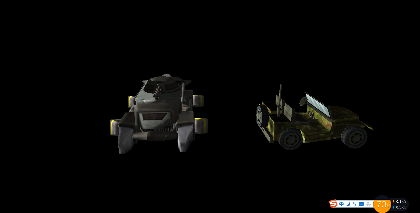
更多学习参考Drawing polygons & OpenGL-Draw-Call-Code-Study-Analysis
Instanced Rendering
“Instanced rendering means that we can render multiple instances in a single draw call and provide each instance with some unique attributes.”(在一次draw call里绘制多个同一个instance)
Using the Instance Counter in Shaders:
The index of the current instance is available to the vertex shader in the built-in variable gl_InstanceID. This variable is implicitly declared as an integer. It starts counting from zero and counts up one each time an instance is rendered.
Instancing Redux:
Steps:
- Create some vertex shader inputs that you intend to be instanced
- Set the vertex attribute divisors with glVertexAttribDivisor()
- Use the gl_InstanceID built-in variable in the vertex shader
- Use the instanced versions of the rendering functions such as glDrawArraysInstanced() ……
1 |
|
Final Effect: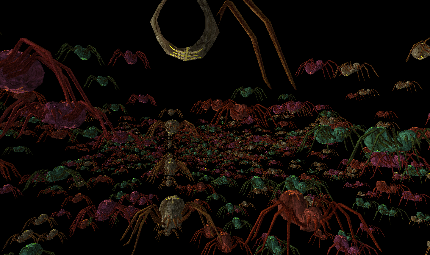
Note:
gl_InstanceID is always present in the vertex shader, even when the current drawing command is not one of the instanced ones.
GLFX - An OpenGL Effect Library
首先让我们了解一下,什么是Effect file?
“An effect is a text file that can potentially contain multiple shaders and functions and makes it easy to combine them together into programs. This overcomes the limitation of the glShaderSource() function that requires you to specify the text of a single shader stage.”
可以看出,通过effect file,我们可以把所有shader写到一个文件里,不用再创建针对各个stage的shader的文件。这样一来我们在shader里定义的结构体就能在多个shader共用。
那什么是GLFX了?
“Effects system for OpenGL and OpenGL ES”
GLFX提供了方便的接口去转换effect file到GLSL program.
接下来让我们看看,如何使用GLFX支持effect file。
- 编译生成并添加glfx.lib到引用
- 包含glfx.h头文件
1 |
- 解析effect file
1 | if (!glfxParseEffectFromFile(effect, "effect.glsl")) { |
- 编译并启用Effect program
1 | int shaderProg = glfxCompileProgram(effect, "ProgramName"); |
- Release effect file after we no longer use it
1 | glfxDeleteEffect(effect); |
接下来看看编写Effect file有哪些不同于GLSL Shader的地方
- 使用’program’ key word去定义一个program,并在其中包含各Shader的调用路口
1 | program Lighting |
- 使用’shader’ key word去定义各shader stage的函数入口而非void
1 | shader VSmain() |
- 可以定义多个program在Effect file中,只需通过glfxCompileProgram()去指定编译特定program即可
- 因为所有shader内容都写在一个文件里了,所以支持共用struct定义,不用再定义一个个in or out variables
1 | struct VSoutput |
- 可以在Effect file里直接包含其他Effect file(但新包含的文件并不参与GLFX Parse,并且该文件是以直接插入的形式,所以该文件只能包含pure GLSL不能包含GLFX里的一些定义方式)
1 |
- 通过:后缀,快速定义attribute的位置而不是通过一个个layout(location=……)
1 | struct VSInput2 |
- 一些关键词如’flat’,‘noperspective’修饰的变量不能放在Effect file定义的struct里,只能通过interface去定义,而interface又必须通过再次拷贝内容到struct才能在Effect里使用
1 | be passed between shader stages. If you need to pass it as a whole to another function you will need to copy the contents to a struct. For example: |
- glfxc工具,可以用于外部单独解析编译Effect file,提前查看是否有问题(这个本人没有试,因为我没有编译出glfxc。)
glfxc
Final Effect:
Note:
“GLFX is dependant on GLEW(注意GLFX是依赖于GLEW的,编译GLFX的时候会需要指定GLEW的路径)”
Deferred Shading
在了解什么是Deferred Shading之前,我们需要了解与之对应的Forward Rendering。
What is forward rendering?
Forward Rendering就是我们之前一直采用的,给GPU传入geometry,texture数据,然后每一个vertex通过pipeline(VS,GS,FS……)得出最后的render target显示在screen上。
下图来源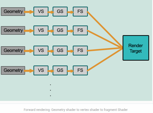
既然有了Forward Rendering,为什么我们还需要Deferred Shading了?
Since each pixel of every object gets only a single FS invocation we have to provide the FS with information on all light sources and take all of them into account when calculating the light effect per pixel. This is a simple approach but it has its downsides. If the scene is highly complex (as is the case in most modern games) with many objects and a large depth complexity (same screen pixel covered by several objects) we get a lot of wasted GPU cycles. (第一个问题大量无用的光照计算。简单的说就是传统的Forward Rendering是针对每一个传入的顶点都会经历一套完整的Pipeline(包含参与光照计算)。但在大型游戏里,会有很多物体(顶点数据),但最终只有离camera最近或者透明的一部分物体会显示在屏幕上,这样一来,针对每一个顶点都计算光照就会做很多无用功。)
When there are many light sources, forward rendering simply doesn’t scale well with many light sources.(因为Forward Redenring每一个pixel都会参与光照计算,当场景里光照很多的时候,无论光源对物体的影响有多微弱或多强,Forward Rendering都会一一计算这些光照对物体的影响,这样会导致大量的光照计算。)
而Deferred Shading却没有上述问题。
那么让我们来了解一下什么是Deferred Shading
deferred shading is a screen-space shading technique. It is called deferred because no shading is actually performed in the first pass of the vertex and pixel shaders: instead shading is “deferred” until a second pass.
下图来源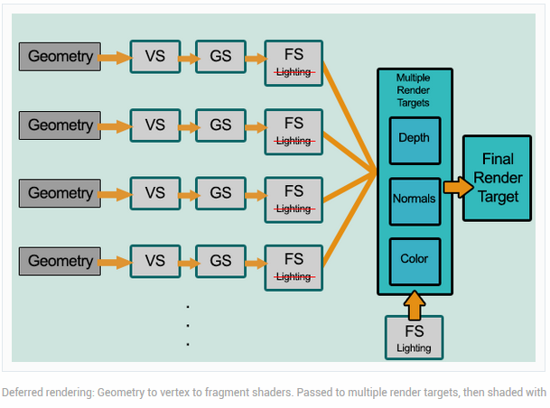
从上面我们只能看出,Deferred Shading是针对scree-space而非每一个物体的vertex。并且deferred shading是由两个pass构成,第二个pass才是真正的shading。
接下来让我们看看这两个pass:
- Geometry Pass. Data that is required for shading computation is gathered. Positions, normals, and materials for each surface are rendered into the geometry buffer (G-buffer) using “render to texture.(Multiple Render Targets (MRT)(在第一个pass我们并不像Forward Rendering把所有光照计算相关的数据传入FS而是存入geometry buffer(G-buffer)用于第二个pass进行真正的Shading。因为我们存储在G-buffer里的数据都是经过rasterizer的,所以在G-buffer里我们只存储了通过depth test的pixel,这样一来我们在第二次用G-buffer数据计算光照的时候就避免了无谓的光照计算(这里指没通过depth test的pixel))
让我们来看看G-buffer都存储些什么数据,下图来源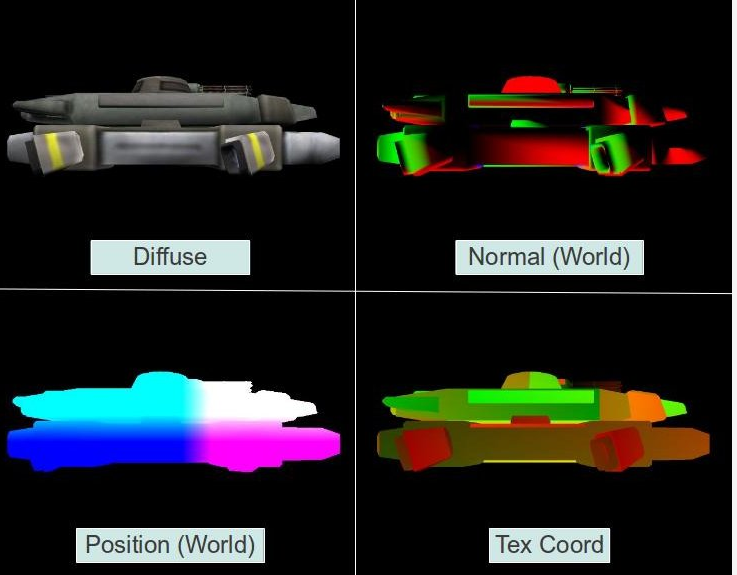
可以看出,我们存储了所有参与光照计算所需要的数据。
Geometry Pass的主要目的是生成4个关于Position,Diffuse,Normal,TexCoord的纹理贴图和一个关于Depth的纹理贴图。
Geometry Pass主要由以下几个步骤:- 创建m_FBO
1 | bool GBuffer::Init(unsigned int windowwidth, unsigned int windowheight) |
2. 创建4个纹理贴图分别Attach到m_FBO的GL_COLOR_ATTACHMENT*上。单独创建1个纹理贴图Attach到m_FBO的GL_DEPTH_ATTACHMENT上
1 | bool GBuffer::Init(unsigned int windowwidth, unsigned int windowheight) |
3. 指定需要从FS中输出的Position,Diffuse,Normal,TexCoord绘制的color buffer
1 | bool GBuffer::Init(unsigned int windowwidth, unsigned int windowheight) |
4. 调用Geometry Pass生成对应的纹理贴图信息
1 | static void DSGeometryPass() |
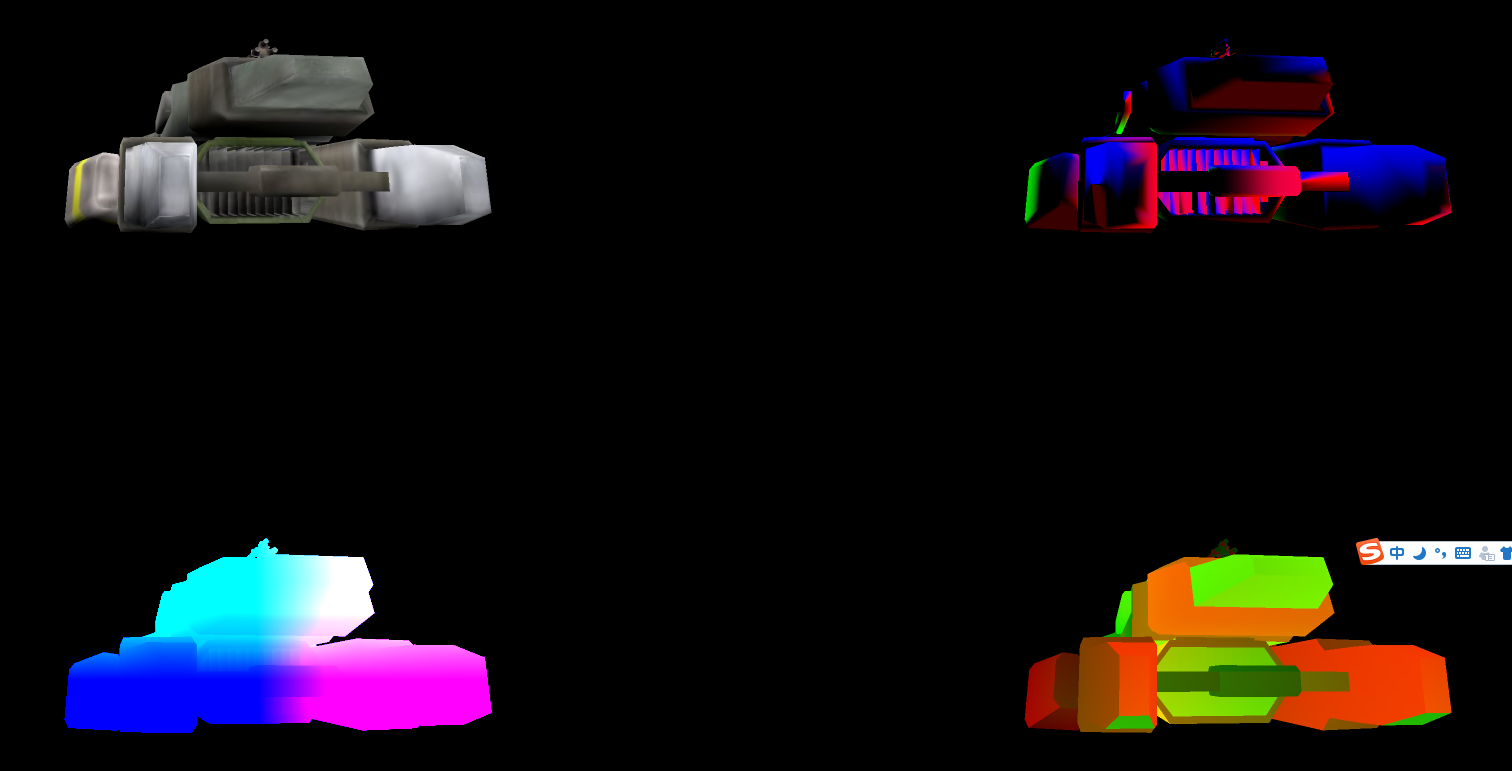
5. 将生成的4个Color Texture复制到FrameBuffer 0里,然后渲染到屏幕上
1 | static void DSLightPass() |
Final Effect:
在真正的Deferred Shading中,有几个需要注意的点。
第一个点,我们不需要讲生成的四个Color Texture显示在屏幕上,所以最后一步是可以省去的。
第二个点因为Geometry Pass只需要存储closest pixel,所以我们需要开启GL_DEPTH_TEST,并且设置glDepthMask(GL_TRUE)来防止其他pass写入我们的fbo的depth buffer。
最终geometry pass代码如下:
1 | void DSGeometryPass() |
第三个点,因为Lighting Pass里参与计算的的TexCoordnate信息可以通过下列算式计算出来,所以出于节约内存,我们可以不必生成TexCoordnate的Texture(即只需要Position,Diffuse,Normal和Depth(这个后续会用到)四个贴图)。
1 | vec2 CalcTexCoord() |
第四个点,因为我们生成的Texture最终会用于Screen的1对1映射计算,所以我们需要把我们生成的Texture指定filter。
1 | bool GBuffer::Init(unsigned int WindowWidth, unsigned int WindowHeight) |
- Lighting Pass. A pixel shader computes the direct and indirect lighting at each pixel using the information of the texture buffers in screen space.
在第二个Lighting Pass里我们只需要用我们在Geometry Pass存储的数据来进行pixel by pixel的光照计算即可,因为我们存储的texture是针对screen space的,所有存储的pixel都是通过了depth test的,所以在Deferred Shading里,我们只针对通过了depth test的pixel进行了光照计算。
下面我们来看看如何通过已经存储的Position,Diffuse,Normal,Depth信息来得出最终的光照颜色。首先让我们看看整体的轮廓。
1 | static void RenderCallbackCB() |
1. 开启混合模式,因为Deferred Shading现在是每一个pixel都会针对所有相关的光照进行计算,最终的结果将有所有光照计算叠加而成。(因为我们不需要再从我们生成的fbo读取数据了(直接从生成的texture里去读),所以不需要再绑定到生成的fbo上,而是绑定到默认的fbo上,这样一来我们只需设置并绑定我们对应的Texture即可)
1 | void GBuffer::BindForReading() |
2. 每一个Pixel针对场景里的Point, Direction, Spot Light进行计算得出最终颜色。这里要针对每一种光照进行说明,如何触发正确的计算。
Direction Light因为是全局光,所以我们需要针对每一个Pixel进行计算,这里我们通过一个铺满屏幕的Quad Mesh来触发计算。
Direction Light:
1 | light_pass.vs |
Point Light因为是范围光,所以我们需要知道Point Light所影响的范围去触发对应Pixel的光照计算。这里涉及到一个Point Light的Point Light光照削弱方程。这里我也没详细看了,想了解的可以去看一下。通过方程我们得出了Point Light的有效范围,这样一来我们只需要以Point Light所在位置为圆心绘制一个Sphere就能触发正确的Point Light光照计算了。
Point Light:
1 | // Shader没什么变化,只是通过Texture去读取相关数据,这里就不重复了。 |
实现的过程中我遇到点问题,所以也没有去实现Spot Light,个人认为应该是通过cone(圆锥体)去模拟Spot Light的范围,通过光照削弱方程去计算有效范围。
这里说一下我遇到的问题(没有解决),如果大家有什么头绪,欢迎提出来。
描述上来说,我通过官网的教程根据source code编写后,发现我的只有当camera离的很近的时候才会显示一个box(最初怀疑是PersProjInfo设置的zFar导致的,后来查看是一模一样的。但通过修改源代码的zFar=2.0我得到了相同的结果,但这里无论我如何修改zFar,我的示例始终只有靠近box的时候才显示一部分。)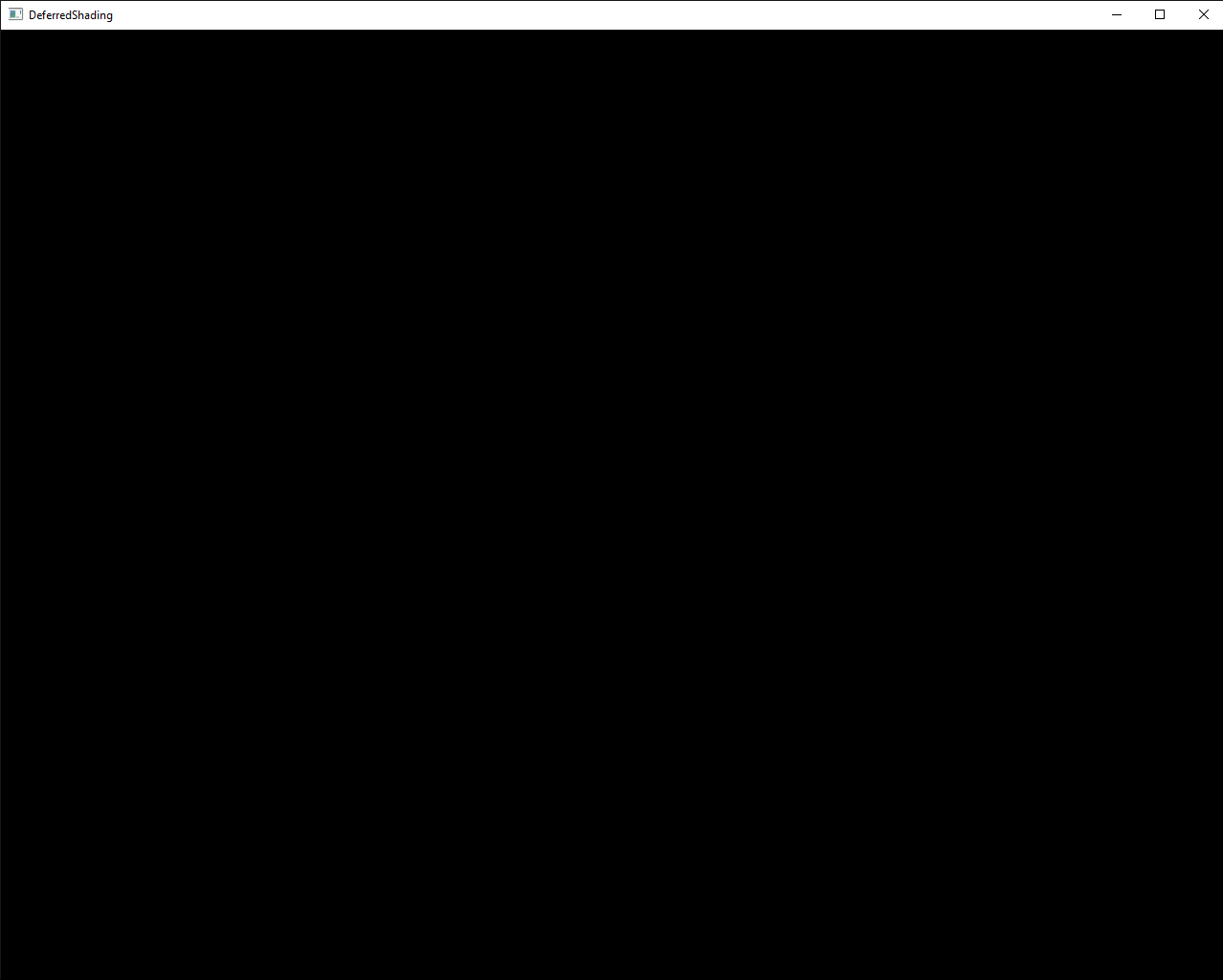
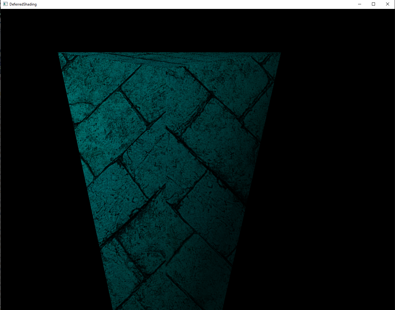
1 | // Source Code |
通过上述方法计算后,我们得出了我们Deferred Shading后的效果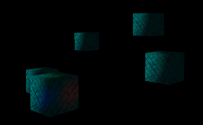
但上述方法还有一些问题:
当我们靠近Point Light的时候,Point Light光照消失了(这是因为我们之渲染front face,当Camera进入Light Sphere的时候Sphere被cull away了,所以也就不会触发Point Light的计算了。)
因为Sphere是针对我们生成的Screen Space的Texture而言的,所以有时候有些object其实不在sphere内但在sphere所在的screen space上就参与了计算,这样就错误的给某些object计算了point light。
解决第二个问题,需要用到Stencil Buffer。
在此之前让我们先来了解下什么是Stencil Buffer?
A stencil buffer is an extra buffer, in addition to the color buffer and depth buffer (z-buffering) found on modern graphics hardware. The buffer is per pixel, and works on integer values, usually with a depth of one byte per pixel.
简单的想,可以把Stencil Buffer理解成PS里面的模板,只有Stencil Buffer里面的数据(数据可以修改)不为0的时候特定像素才能通过。真是因为这个特性我们可以控制哪些pixel参与Point Light光照计算。
Stencil Buffer用于Stencil Test,Stencil Test是针对每一个像素调用,就像我之前说的类似PS的模板。
来我们来看个简单的Stencil Buffer效果,下图来源: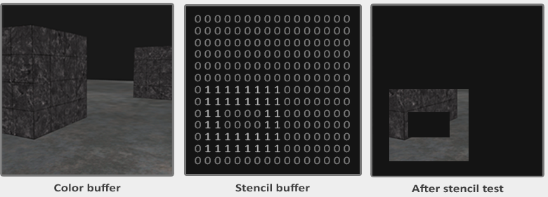
我们可以指定Stencil Buffer里的值如何修改,什么时候修改。
接下来让我们来看看如何通过Stencil Buffer来解决第二个问题:
以下引用至
- Render the objects as usual into the G buffer so that the depth buffer will be properly populated.
- Disable writing into the depth buffer. From now on we want it to be read-only
- Disable back face culling. We want the rasterizer to process all polygons of the sphere.
- Set the stencil test to always succeed. What we really care about is the stencil operation.
- Configure the stencil operation for the back facing polygons to increment the value in the stencil buffer when the depth test fails but to keep it unchanged when either depth test or stencil test succeed.
- Configure the stencil operation for the front facing polygons to decrement the value in the stencil buffer when the depth test fails but to keep it unchanged when either depth test or stencil test succeed.
- Render the light sphere.(only when the stencil value of the pixel is different from zero)
关键思想是通过判断object的front和back face是否在sphere的front和back的前面或后面来修改stencil buffer的值,然后通过该值得出我们所需绘制的pixel。
请看下图: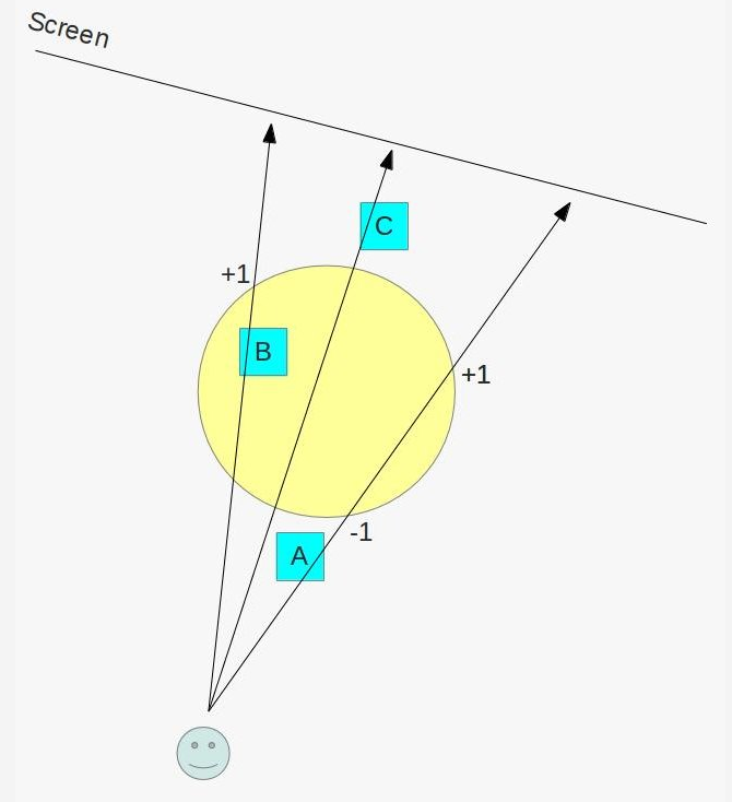
sphere的front和back face都在物体A的后面,物体C的前面,就物体B而言,front face在物体B之前,back face在物体B之后。
所以通过5,6步骤设定的规则,只有物体B所在的所在的pixel的stencil buffer值大于0
上面的2-6算作Stencil Pass,用于得到哪些物体参与Point Light Sphere的计算。
第7步才是真正光照计算。
接下来让我们看看代码实现:
- 针对每一个Point Light开启stencil test并在进行关照计算之前调用stencil pass得出需要参与计算的pixel
1 | null_technique.vs |
- 调用Point Light Pass通过stencil buffer对特定pixel进行光照计算
1 | void GBuffer::BindForLightPass() |
- 最后渲染G buffer里计算得出的图像(之前我们绘制到了G buffer的GL_COLOR_ATTACHMENT4里)
1 | void GBuffer::BindForFinalPass() |
Final Effect: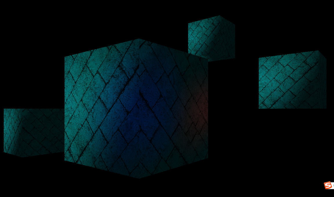
OpenGL Utility
Open Asset Import Library
“Open Asset Import Library is a portable Open Source library to import various well-known 3D model formats in a uniform manne”
assimp
“assimp is a library to load and process geometric scenes from various data formats. It is tailored at typical game scenarios by supporting a node hierarchy, static or skinned meshes, materials, bone animations and potential texture data. The library is not designed for speed, it is primarily useful for importing assets from various sources once and storing it in a engine-specific format for easy and fast every-day-loading. “
Note:
个人理解,assimp主要是提供了对多种格式模型的数据解析,并抽象了所有数据到aiScene这个类里。
通过aiScene我们可以去访问模型数据里的顶点数据,纹理数据,材质数据等。
我们通过这些数据最终去作为我们的顶点数据创建顶点buffer,作为纹理数据创建纹理贴图,最终绘制出我们的模型。
源代码参考OpenGL Tutorial 22
open3mod
“open3mod is a Windows-based model viewer. It loads all file formats that Assimp supports and is perfectly suited to quickly inspect 3d assets.”
主要用于快速查看各种资源格式的模型。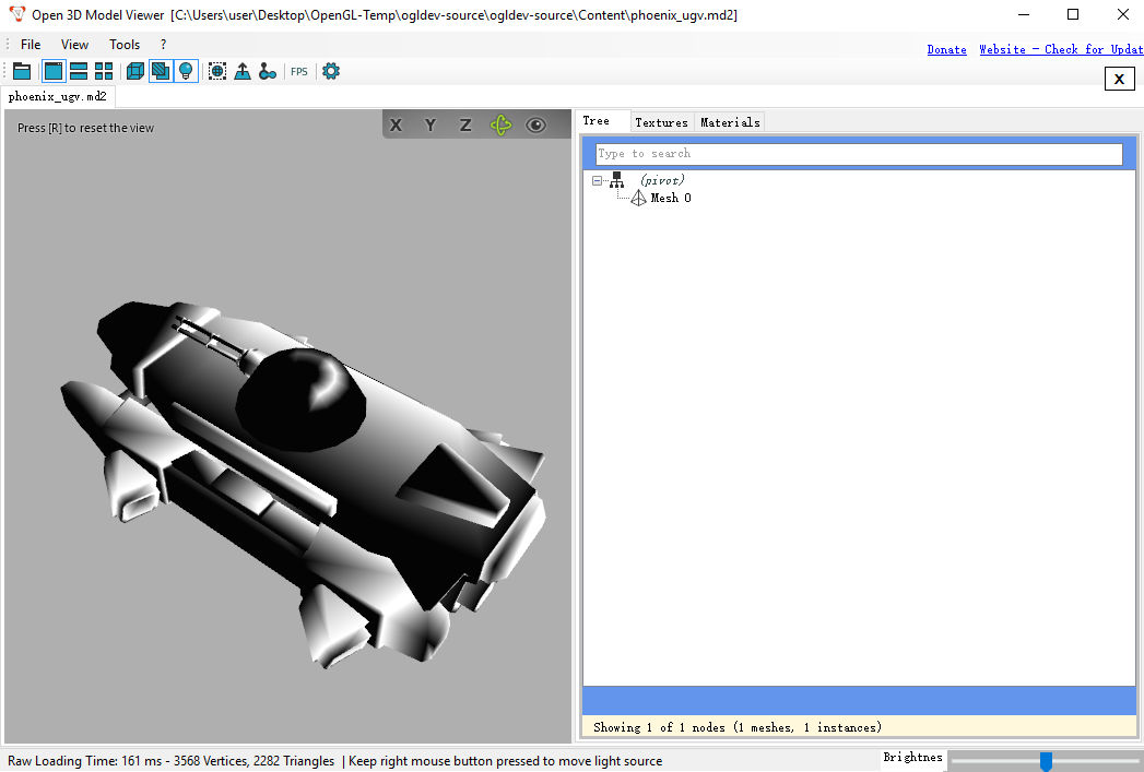
GIMP
GNU Image Manipulation Program (GIMP) is a cross-platform image editor available for GNU/Linux, OS X, Windows and more operating systems.
GIMPDownloadLink
gimp-normalmap plugin that supports to export normal map from texture
gimp-normalmapDownloadLink
通过GIMP和gimp-normalmap插件,我们可以从texture中导出normal map使用。
GLSL Debuger
Nsight
NVIDIA® Nsight™ is the ultimate development platform for heterogeneous computing. Work with powerful debugging and profiling tools that enable you to fully optimize the performance of the CPU and GPU. - See more at: http://www.nvidia.com/object/nsight.html#sthash.Hc8TfPMs.dpuf
Nsight是NVIDIA开发的一套协助GPU开发的工具。
优点:
- 支持直接调试GLSL和HLSL等着色器语言
- 和VS完美集成
缺点:
- 硬件限制比较多(比如主要针对NVIDIA公司的显卡)
Nsight Visual Studio Edition Requirements
OpenGL proiler, debugger
gDEBugger
gDEBugger是一个针对OpenGL和OpenCL开发的一套调试器,分析器和内存分析器等协助工具。
通过gDEBugger我们可以查看在某一贞关于OpenGL相关的大量信息(比如Uniform值,OpenGL的各个状态,Draw call次数等)
可以查看到OpenGL的一些状态,比如GL_CULL_FACE: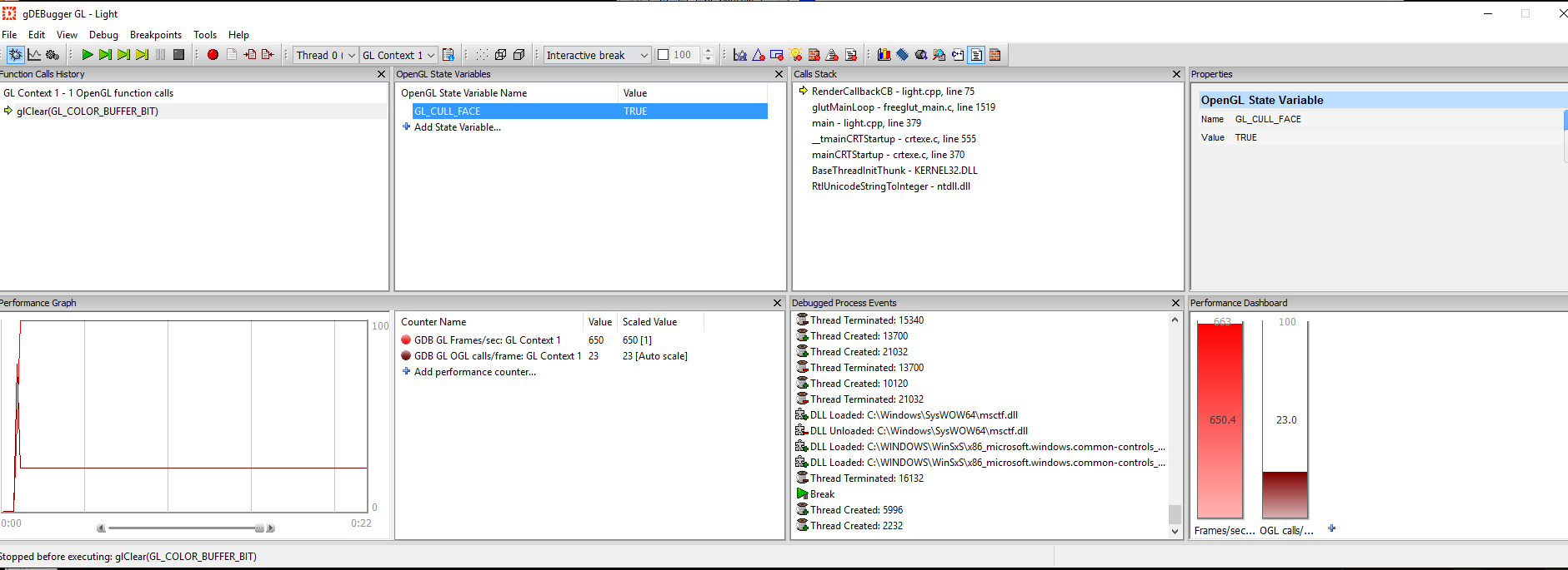
可以查看Shader的一些信息,并且可以编译Shader等: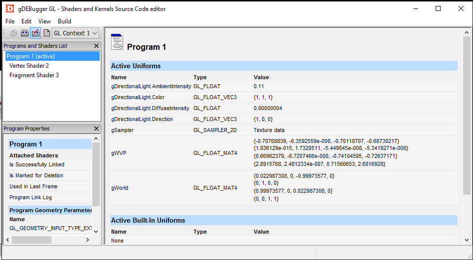
Reference Website:
OpenGL 4 reference page
client-server 模式
OpenGL Execute Model
X Window System
OpenGL Tutorial
OpenGL Windows & Context
Creating an OpenGL Context (WGL)
OpenGL Context
Window and OpenGL context
OpenGLBook.com Getting Started
Note:
OpenGL uses right-handed coordinate system (OpenGL使用右手坐标系)
