视野范围动态刷新
前言
一直以来除了学图形学渲染的时候接触到摄像机的坐标系转换,平时对于摄像机照射范围的原理知之甚少。当我们在做可视区域判定时(比如SLG游戏只会创建可视区域范围内的东西),我们需要计算出当前摄像机的照射范围,然后动态请求可视化区域内需要新增显示的地图对象。实现可视区域动态请求显示这一步离不开对摄像机可视区域的计算。本文正是为了深入解决可视区域计算,深入理解摄像机照射原理,实现一套可视化摄像机照射区域和动态可视区域物体动态创建的工具。
摄像机
摄像机目前分为透视摄像机和正交摄像机,前者有深度概念有透视效果会近大远小,后者忽略深度类似是把3D投射到2D平面的效果。
首先我们来看一下透视摄像机的投影图:
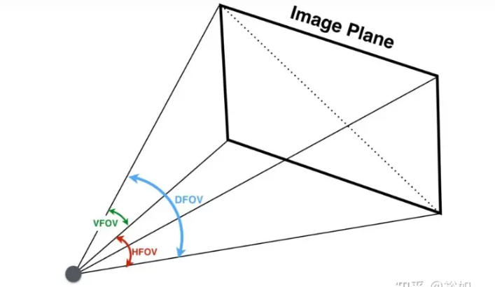
其中FOV是透视摄像机里很重要的一个参数,Fov指的是相机视场(Field of View)张角。
FOV指的是图中的DFOV,即对角线视场角。
VFOV指的是垂直视场角,VFOV是受屏幕高度影响
HFOV指的是水平视场角,HFOV是受屏幕宽度影响
摄像机照射区域
摄像机的可见范围计算原理:
- 不考虑摄像机是正交还是透视,通过将屏幕四个角映射到世界坐标系(屏幕坐标到世界坐标),得到从摄像机到摄像机四个角的射线数据
- 计算四条射线到在指定平面的交叉点计算,得出的4个交叉点构成的形状就是我们要的透视摄像机在指定平面上的投影形状
仅仅是需要知道透视摄像机四条射线的前提下,我们不需要自己去计算DFOV,VFOV,HFOV等数据。
1 | /// <summary> |
- 得到屏幕四个角映射的射线数据后,利用射线和平面的交叉计算得到指定平面交叉的点就能得到我们要的平面照射区域
1 | /// <summary> |
1 | /// <summary> |
从上面可以看到无论是areaPointsList还是rectPointList都返回了5个顶点数据,第五个是屏幕中心映射的点。
之所以返回矩形的映射区域,是为了简化后面透视摄像机梯形判定顶点复杂度,简化成AABB和点的交叉判定。
摄像机照射区域可视化
得到了屏幕映射的顶点数据,通过构建线条数据,我们就能利用GUI相关接口画出可视化可见区域了
1 | /// <summary> |
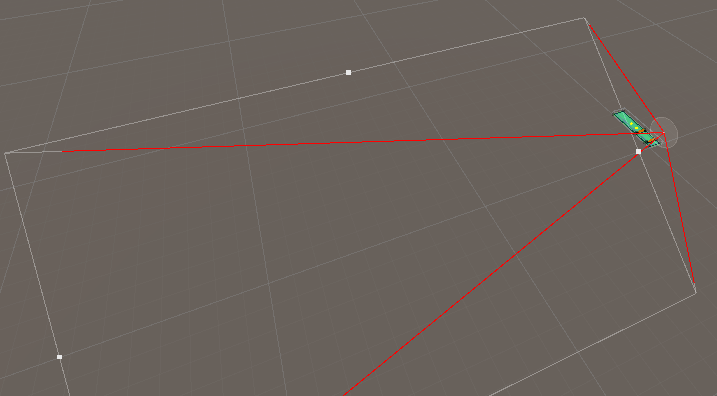
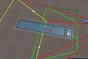
摄像机照射区域可视化:
可以看到黄色是远截面照射区域,深绿色是近截面照射区域,浅绿色是摄像机近截面换算成矩形后的区域,红色线条是摄像机近截面和远截面射线,
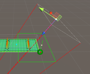
透视摄像机效果如下:
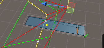
正交摄像机效果如下:
摄像机照射区域动态刷新
动态区域刷新核心要点:
- 映射屏幕4个点得到四条摄像机照射射线,通过计算4条射线与指定平面的交叉点得到照射区域,简化照射区域形状到矩形,将物体是否在照射区域转换成点与AABB交叉判定
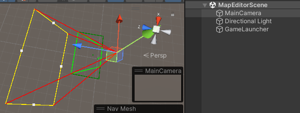
实战摄像机照射区域动态刷新参考地图编辑器:
实战效果图:
Note:
- 屏幕4个顶点计算顺序依次是左下,左上,右上,右下
重点知识
- 不考虑摄像机是正交还是透视,通过将屏幕四个角映射到世界坐标系(屏幕坐标到世界坐标),得到从摄像机到摄像机四个角的射线数据,然后将摄像机区域计算转换成计算四条射线到在指定平面的交叉点计算,得出的4个交叉点构成的形状就是我们要的透视摄像机在指定平面上的投影形状
- FOV分为DFOV(对角线视场角),VFOV(垂直视场角,受屏幕高度影响)和HFOV(水平视场角,受屏幕宽度影响)
- 透视摄像机看多少不仅受FOV影响还受屏幕分辨率影响
- 摄像机指定位置平面照射形状可以转换成摄像机4个射线和平面的相交检测处理
博客
GitHub
Reference
根据相机参数计算视场角(Filed of View, FOV)
